- +1 919 200-0292
- info@antennatestlab.com

The 3D Spherical Coordinate System
The 3D Spherical Coordinate System
Understanding Spherical Coordinates
Antenna Test Lab Co performs 3D spherical evaluations using Phi axis (roll) and Theta (turntable) stepping per the “Great Circle Cut System”. This way, native results are available directly in the standard preferred spherical coordinate system.
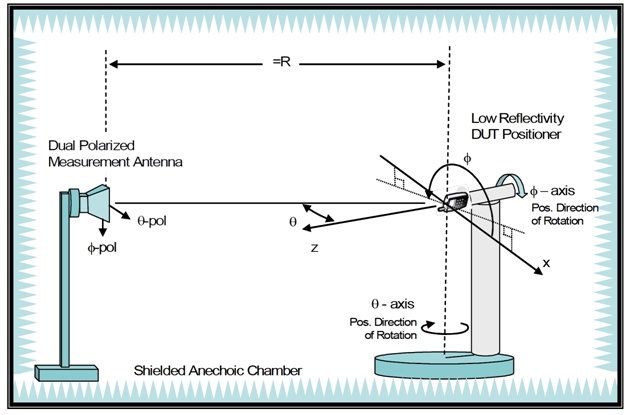
This enlargeable figure shows the Theta axis (turntable or azimuth control) with the Phi axis “roll positioner” (or elevation control) on top of it. Our positioners are fiber-optically controlled, and made of all plastic materials so as not to absorb RF energy. The rate of turn is 3 RPM (20 seconds) with a positioning accuracy of better than 0.1 degree. Our Photos of the laboratory show sample mounting arrangements for various items. Our chamber antennas can cover 300 MHz to 40 GHz. For increased throughput speed, our lab uses three-port VNA measurements and quad ridge horns to simultaneously take vertical and horizontal polarized antenna gain measurements.
It may sound complicated, but it is not. You can download our 3D plotting software here. Then download one of the 3D tested example antennas and make your own desktop plots. You could start with Example #1. You can even brush up on antenna testing methods and terminology here.
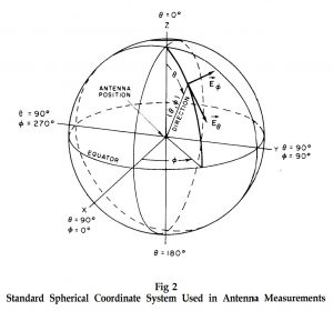
Measurements are logged in tables of Theta and Phi spherical coordinates, per IEEE Std 149-1979, “Test Procedures for Antennas”. The standard IEEE antenna coordinate system is illustrated below. The spherical coordinates relate to the Cartesian axes as shown in the click-to-enlarge diagram to the left.
Evaluate Your Antenna
Ready to find out more about your antenna … partner with an antenna evaluation company and never be “in the dark” again! Contact us here.