- +1 919 200-0292
- info@antennatestlab.com

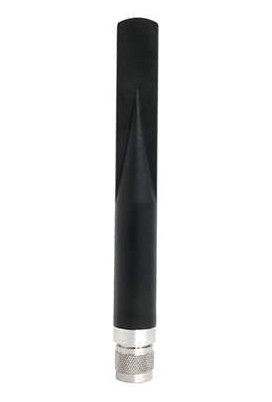
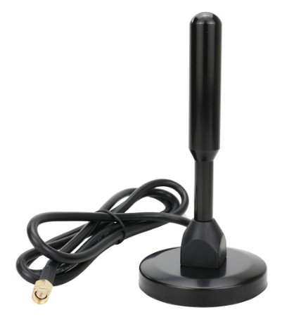
Alpha Network ADA-915-5ACM Helium Antenna 5dBi
Search results for:
Alpha Network ADA-915-5ACM Helium Antenna 5dBi
Purchased for $25 from Amazon here on February 8, 2022
This antenna was given a full 3D spherical swept gain test program with gain measured in over 400 physical directions and at 200 frequencies. This kind of testing helps you visualize the full radiation sphere. With normal intended installation the antenna would be vertical (the Z axis in these diagrams) with intended gain towards the horizon (from the sides of the antenna) in the XY plane.
When marketed as a 5 dBi antenna, one would expect the gain in the “sideways” directions to be approximately 5 dBi. Actual measured gain was as follows: 902 MHz +1.3 dBi; 915 MHz +0.9 dBi; 928 MHz +0.4 dBi.
While a peak gain of +2.6 dBi was measured, it was about 10 degrees above the horizon, and not really very useful. So this antenna is falling short of the expected sideways gain/directivity by about 4 dB. It is typical of consumer antennas to have over stated gains, so these results are not surprising. It is fairly small and may offer some convenience over larger outdoor antennas. The images below are all click-to-enlarge.


Helium Network Antenna Reviews
We keep getting asked “what is the best Helium miner antenna?”
While we are not in the business of selling or even recommending antennas, we have decades of antenna testing experience, and we are always willing to help customers. So just for fun, we have bought a selection of popular “helium miner” antennas from Amazon and eBay. Then we do what we do best – proper engineering lab testing and documenting objective antenna testing results.
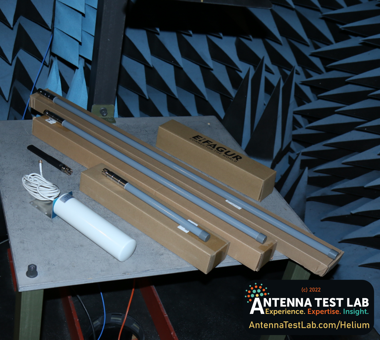
These antennas operate in the unlicensed 902-928 MHz ISM band, and are marketed to consumers and hobbyists. Unfortunately, the marketing tendency is to inflate antenna gain numbers and make unsubstantiated claims – intended to sell in to a retail market where consumers don’t understand antenna specifications or have the means to verify performance. These antennas are made by countless offshore shops, then copied ad nauseam with the same flaws and false claims. Bought by importers at online tradeshows or quasi-wholesale websites like Alibaba. Then private labeled with disposable brands that have no long term reputation to protect. So please keep your expectations low.
In fact, one antenna branded Eifagur had ridiculous claims of 10 dBi omni-directional gain, that we couldn’t resist disproving. So here are some real laboratory results and miner antenna comparisons. Hopefully actual independent laboratory testing will help you chose the best antenna and achieve the best range in your network.
 | Alpha Network AOA-915-5ACM, $25, and specified at 5 dBi. Detailed results here. |
 | Bingfu 3dBi (14 inch), $30. Detailed results here. |
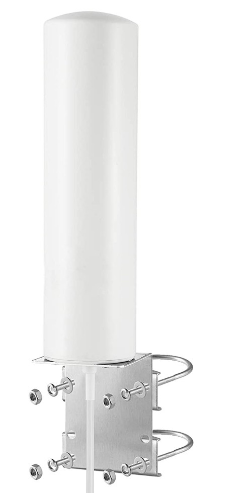
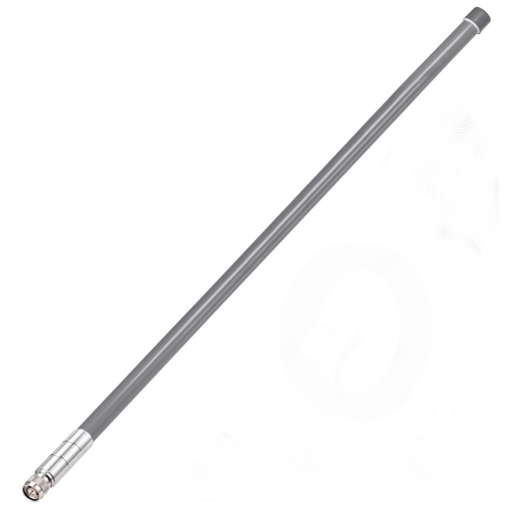 | Bingfu 5.8dBi (31.5 inch), $39. Detailed results here. |
 | Bobcat (indoor), and specified at 4 dBi. Detailed results here. |
 | Eifagur YCF-6927, $45, and specified at 10 dBi. Detailed results here. |
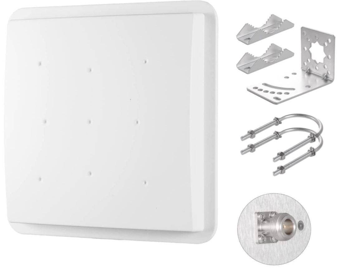 | Eifagur 12 dBi outdoor panel antenna, $99, and specified as circularly polarized. Detailed results here. |
All of the “miner” antennas that we have evaluated had significantly less useable gain that advertised. “Real world testing” sounds great, but this over-the-air testing is far too variable to spot specification deviations. Nevertheless, there is still plenty of web content from bloggers and enthusiasts who are “evaluating” antennas.
A few thoughts on the subject of antenna gain. We have this basic article on gain here, and a further explanation of the relationship between gain and directivity. Keep in mind that gain is a function of direction and frequency. This means that an antenna has a fully 3 dimensional gain pattern, and it is different for each frequency. So describing an antenna with a single gain figure can be misleading (sometimes intentionally) – because that gain may be in a useless direction or at an irrelevant frequency. It may even be “fudged up” by 3 or 4 dB for sales-appeal. That’s why commercial customers and design houses pay laboratories like us to do 3D swept frequency patterns on their antennas.
What antenna gain do I need? Where should it be located?
If you are trying to create a terrestrial radio network (that’s what you are doing with your Helium hotspot radio gateway) you need your antenna outdoors and as high as possible. To get the best coverage, locate your antenna up on a pole/mast/tower above your roofline. Roof mounts and masts are helpful here, and investing in better coverage pays you back in income. Omni directional antennas with actual gains from 6 to 8 dBi are great choices, if you give them unencumbered height. Indoor antennas (and their sellers) that promise awesome results are misleading you – that’s like buying magic solar cells that work “great” indoors … but indoors will always be a compromise and severely limit the performance of your miner hotspot (and solar cells). That’s NOT to say that indoor antennas (or solar cells) don’t work – it’s not black and white – they just have far less range and radio coverage that a properly located outdoor antenna (and less income for the same mining hardware investment).
Coax cable can be very lossy, and can quickly kill any benefits of gain/directivity in your roof mounted antenna. The convenient coaxes supplied with many antennas are 0.200 to 0.250 inches in diameter, but are quite lossy. The cable supplied with the Bingfu antennas measured out to 1.7 dB per 10 feet (at 915 MHz). So using a 30 foot run to to the roof would have a substantial 5 dBi loss. A better strategy would be a quality 0.400 inch cable like Times Microwave LMR400, which would be about 1.4 dB loss for the same 30 foot length.
Also, please seal all of your outdoor connections with rubber tape – those connectors are NOT water-proof! Where the coax enters your house, it must be grounded and protected with a lightning arrestor for your equipment’s safety as well as your own.
Our In-House Ground Planes and Substrates
On Hand To Save You Time
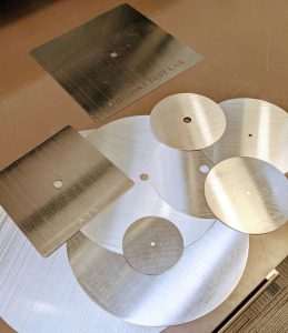
Antennas are usually mounted to something. However, many off-the-shelf antennas are specified for free-space, so you should verify them on your target mounting material or product enclosure. We can supply many ready-to-go metal ground planes, as well as ceiling tiles, glass, drywall, or plywood.
ATL's Ground Plane List
Here is our current inventory of test ground planes| Size | Notes |
|---|---|
| SQUARES | |
| 100 mm Square center hole for SMA Connector | 4 inches |
| 6 Inch Square center hole for SMA Connector | 152 mm |
| 200 mm Squares center holes for Type-N (0.630") and SMA (0.250") Connectors | 7-7/8 inches |
| 10 Inch Square center hole for SMA Connector | 254 mm |
| 300 mm Square center hole for Type-N Connector | 11-7/8 inches |
| 14 Inch Square center hole for SMA Connector | 356 mm |
| 24 Inch Square center hole for Type-N Connector | 610 mm |
| ROUNDS | |
| 100 mm Round center hole for SMA Connector | 4 inches |
| 6 inch Rounds center holes for Type-N (0.630") and SMA (0.250") Connectors | 152 mm |
| 200 mm Rounds center holes for 1.000", Type-N (0.630"), and SMA (0.250") Connectors | 7-7/8 inches |
| 10 inch Rounds, center holes for Type-N (0.630") and SMA (0.250") Connectors | 254 mm |
| 300 mm Rounds center holes for 1.000", Type-N (0.630") and SMA (0.250") Connectors | 11-7/8 inches |
| 16 inch Rounds center holes for 1.250", 1.000", 0.750", Type-N (0.630"), SMA (0.250") Connectors | 406 mm |
| 1 meter rolled edge (car-top simulator) | 39 inches |
Transmitter Pattern Testing Services
Live Antenna Testing From 300 MHz to 18 GHz
- We measure EIRP patterns in 2D (traditional polar plots) or full 3D spherical plots
- Our antenna testing chamber’s frequency range is 300 MHz to 18 GHz on “live antennas”
- You get spreadsheets of your EIRP results in dBm, and the ability to plot any pattern in your swept frequency test, as well as Total Radiated Power calculated from 3D plots
- We can also measure passive antennas
- Our fast turn around time is just days, written quotes are quick, and our online prices are here
Standard Resolution: $350
Our base rate for antenna/transmitter testing is $350 per “run” with a $175 lab setup fee for your project. Choose from either 2D polar plots (two cuts at 2-degree resolution) or 3D spherical plots (10 degree resolution) for your transmitter/antenna combination. We recommend 3D plots for all new, unproven, and non-directional antennas (get 2D/3D help here). The 3D plot allows unparalleled visibility into a device’s true radiation pattern, and often shows features that are impossible to visualize with just 2D polar cuts. Because spherical data covers all directions, our test program will also calculate and include the device’s Total Radiated Power. Spherical antenna patterns frequently surprise first time designers, and deviations from expected or simulated results are due to real-life disturbances such as enclosures, batteries, and attached I/O cables. See all of the benefits here, and learn more with our Educational Pages.
Deliverables For Standard Resolution Live Antenna Transmitter Tests:
- 3D Spherical plots at 10 degree resolution with Vertical, Horizontal, and Total EIRP in dBm
- 2D Polar plots at 2 degree resolution, two orthogonal cuts with Vertical, Horizontal, and Total EIRP in dBm
- The device’s apparent radiated power (EIRP) in dBm is reported at each of the hundreds of pattern directions
- Spreadsheet results allow easy post processing and custom plots like “Peak EIRP In Any Direction”, or “Peak EIRP Above Ground Plane”, and much more
- Photographs of your test setup in the RF anechoic antenna testing chamber
High Resolution $700
This higher-resolution option delivers the same patterns at 5-degree resolution for spherical testing, or 1-degree resolution for 2D polar plots. The frequency setup charge is still $175, with the per-antenna test charge at $700. We have a full price list detailed here.
Maximum Device Size:
Our antenna testing service allows for a maximum test size of 24 x 24 inches with a depth of 24 inches or less.
Circularly Polarized Antenna Testing Services
LHCP/RHCP, Co/Cross Polarization, Axial Ratio
And Cross Polarization Rejection Ratio
Our antenna evaluation service gathers full “vector gain data” during testing, which means your antenna’s gain and phase are both measured. We do this in every test direction, and for every test frequency. Then we do the complex math for you, and report all standard circularly polarized (CP) parameters in easy to understand spreadsheets. Specialized post processing or graphing is made easy when your data is in our spreadsheet format. Virtually any plot can be created, including overlaying co-polarization and cross-polarization parameters on the same graph.
An example of our typical CP spreadsheet report can be found here. We have also created a no-math white-paper explaining CP antenna concepts, which can be found here.

Your test results will include the following data in Excel format:
- All of the features of standard passive antenna testing are included
- LHCP Gain in dBi
- RHCP Gain in dBi
- Total Gain Magnitude in dBi
- Axial Ratio in dB
- Graphs of LHCP, RHCP, and Axial Ratio vs frequency for the preferred antenna direction (data is available for all test directions)
- Raw orthogonal vector gain and phase data
Please Contact Us and see how we can help you with your antenna evaluation.
Antenna Testing Testing Services
Your Choice of Patterns And Resolutions
- We can measure your passive antenna gain patterns in full 3D spherical or 2D polar plots (or even “1D” single-direction)
- Our antenna testing chamber’s frequency range is 300 MHz to 40 GHz on passive antennas, with wide sweeps available to cover your antenna’s entire operating range with one test setup
- You get spreadsheets of your gain results in dBi, and the ability to plot any pattern in your frequency range, as well as Radiation Efficiency vs. Frequency from 3D plots and vector/phase/LHCP/RHCP/Axial data for Circularly Polarized antennas (even in the K bands)
- Our fast turn around time is just days, written quotes are quick, and our prices are listed online
- We can also measure live antennas with EIRP and TRP results in dBm
Standard Resolution Is $350
Our base rate for antenna testing is $350 per antenna with a $175 lab setup fee for your project. Choose from either 2D polar plots (two cuts at 2 degree resolution) or 3D spherical plots (10 degree resolution) for your antenna. We recommend 3D plots for all new, unproven, and non-directional antennas. Not sure … you can get 2D vs. 3D help here. Our 3D plots allow unparalleled visibility into an antenna’s true radiation pattern, and often show features that are impossible to visualize with just 2D polar cuts. Because spherical data covers all directions, our test program will also calculate and include antenna radiation efficiency vs frequency. Spherical antenna patterns frequently surprise first time designers, and we expose deviations from expected or simulated results due to real-life disturbances such as feed line attachment. See all of the benefits here, and learn more with our Educational Pages.
Deliverables For Standard Resolution Antenna Tests:
- 3D Spherical plots (renderable on your desktop PC) at 10 degree resolution with Vertical, Horizontal, and Total gain in dBi
- 2D Polar plots (renderable in Excel) at 2 degree resolution, two orthogonal cuts with Vertical, Horizontal, and Total gain in dBi (a third orthogonal cut is optional)
- Gain in dBi is reported at each of the hundreds of pattern directions, over your entire swept frequency range
- Spreadsheet results allow easy post processing and quick custom plots such as “efficiency vs frequency,” “forward gain vs. frequency,” “front-to-back ratios,” and much more
- Photographs of your test setup in our RF anechoic antenna testing chamber
- Vector gain/phase data with LHCP and RHCP components, as well as axial ratio for Circularly Polarized antennas
High Resolution $700
This higher resolution option delivers the same pattern shapes, but at 5 degree resolution for spherical testing (4 times as many physical test directions), or 1 degree resolution for 2D polar plots. The frequency setup, charge is still $175, with the per antenna test charge at $700. You can see our full price list here.
Maximum Antenna Size:
Our antenna testing service allows for a maximum test size of 24 x 24 inches with a depth of 24 inches or less.
Additional Antenna Measurements
We Do Much More Than Patterns !
Please ask for any of these other antenna testing services along with your request for quotation, or go to our price page to see all testing options and extras on one screen.
- Full price list here.
- Return-Loss and VSWR in spreadsheet form
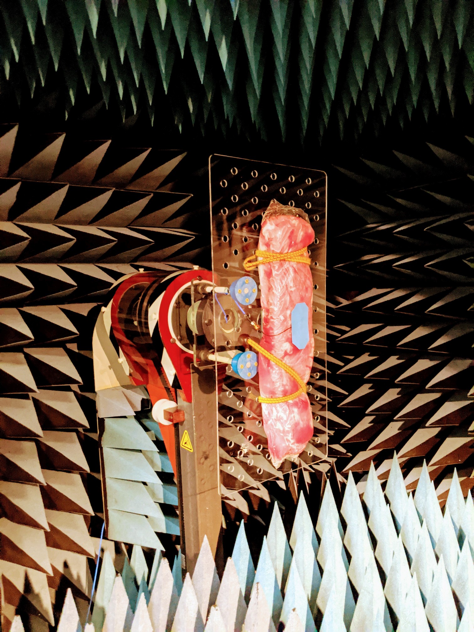
- Mounts for your antenna on our substrates such as glass, plywood, drywall, ceiling tile, ground planes, or animal tissue (for body worn antennas). We have these in-house and ready to go … just ask us
- Additional orthogonal polar cuts in 2D tests
- Half or partial spheres in 3D testing
- 4D movies of 3D spherical frequency swept gain
- Solid printed plastic desktop models of your measured 3D gain results
- Custom pattern resolution levels
- Axial ratio and LHCP/RHCP gain on circularly polarized antennas (also co-polarization and cross-polarization data)
- 1 meter diameter rolled edge ground plane to simulate vehicle-top mounting
- Live antenna transmitter patterns on modulated or pulsed/intermittent devices (CW is not the only option)
- Post Processing like Front-To-Back Ratio vs. frequency
- Beam-width
- Radiation efficiency vs frequency on passive antennas
- Total Radiated Power (TRP) on live antenna transmitters
- An antenna testing educational section has been written for this site.
Services Overview
Antenna Testing Services
Since 2003, our antenna testing service has specialized in giving customers unparalleled insights into their antenna performance. Our comprehensive antenna evaluations offer quick-turn, cost-effective antenna (and live transmitter) patterning and analysis. We cover UHF, and the microwave bands L, S, C, X, Ku, K, and Ka. Our broadband sweeps can cover the 300 MHz to 40 GHz spectrum.
We can remove the risks from your antenna design, procurement, and deployment process. Whether you’re an expert antenna designer, wireless product developer, or a purchaser of antennas, we can arm you with a full radiation performance evaluation. Enjoy some of the many benefits of antenna testing ! Learn more about antenna testing and techniques with our educational pages.
If you are looking for antenna evaluation services, chances are your needs fall into one (or more) of the service areas we focus our expertise on. Click on any of the services below to learn more:
Passive Antenna Gain Pattern Testing
Transmitter EIRP/TRP Live Antenna Testing
Circularly Polarized Antenna Testing
Temperature Controlled Antenna Testing
VSWR and Additional Antenna Measurements
4D Animated Gain Frequency Plots
Antenna Pattern Desktop Models
Online Prices
Click Here For A Quick Quote !
Prices
Antenna Testing Services Made Easy!
Click On Any Feature To Find Out More
If you have any questions or feel like a quick quote, just ask !
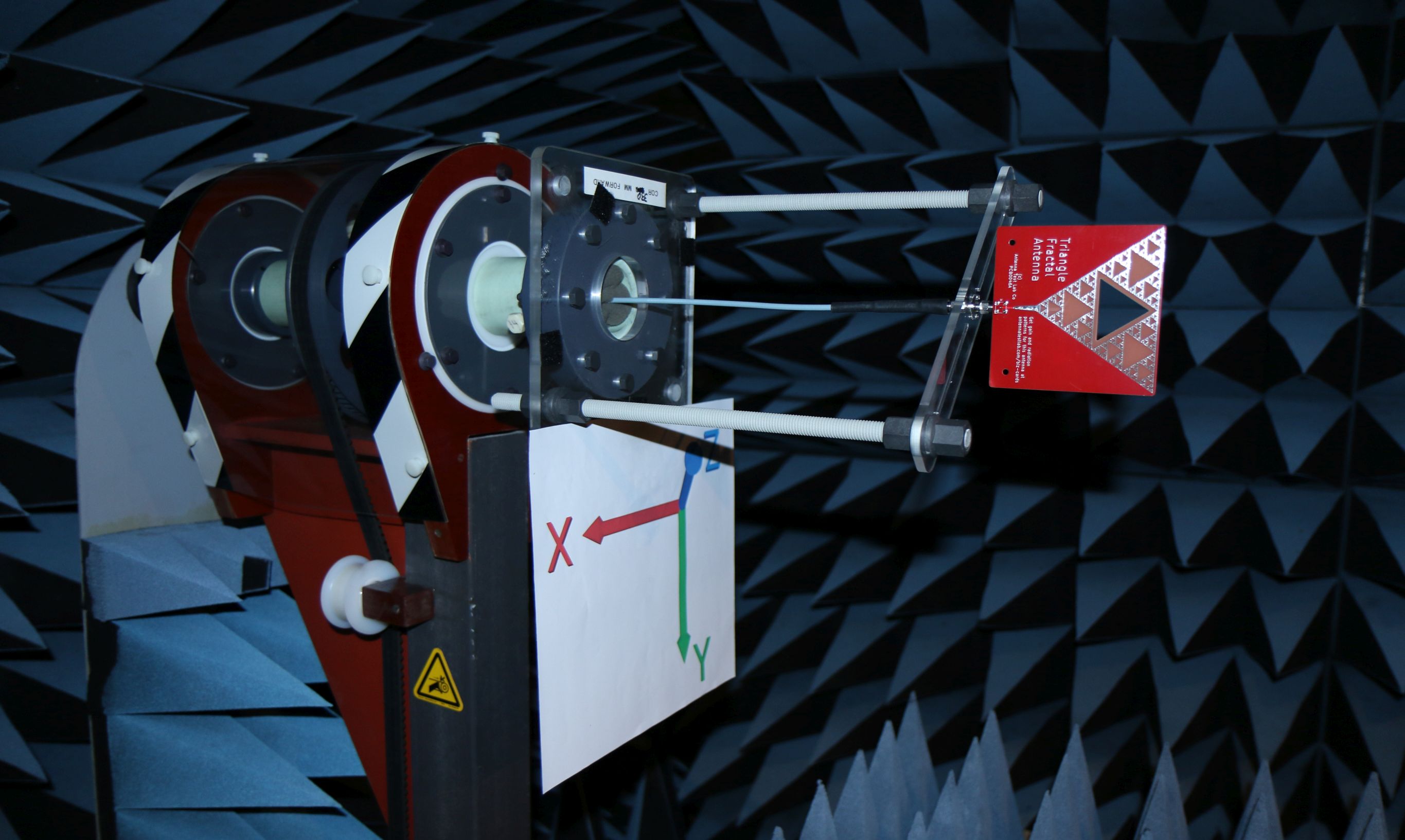
PCB0046 Fractal Antenna
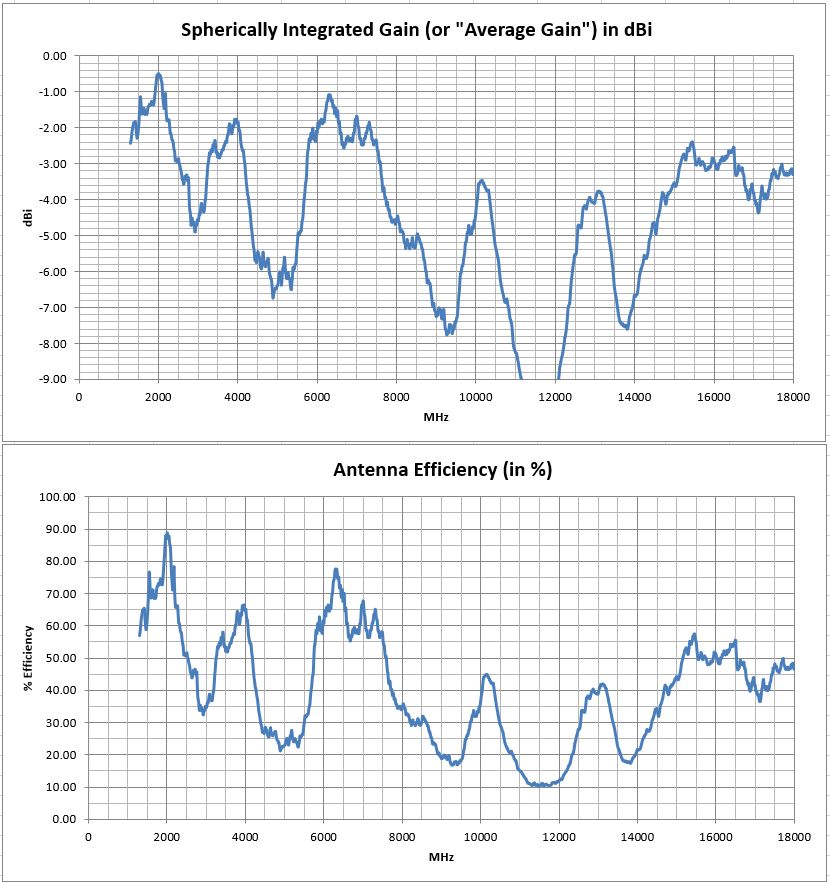
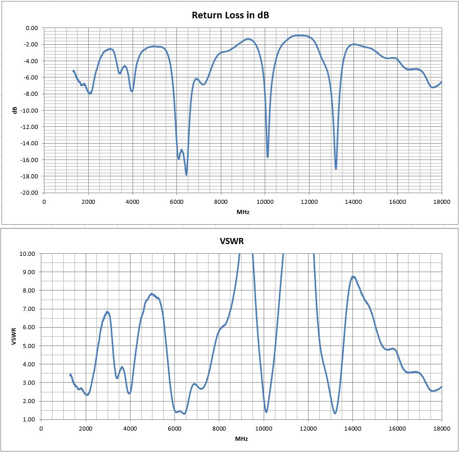
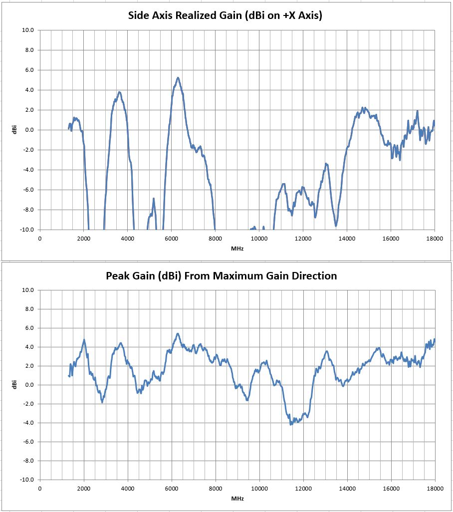
This functional 10 cm “tile” sized fractal triangle pattern antenna works modestly from 1300 MHz to 18 GHz. It does not have the ultra broadband return loss promised in fractal designs, and this implementation has anti -resonances (high VSWR) around 3, 5, 9.5, and 11.5 GHz. Consequently, the average gain and efficiency also display shortcomings at these frequencies. It has sideways gain averaging about 2 dBi as expected from a monopole topology. It has peak gain (meaning it radiates in some direction) that is quite broadband, covering the entire 14:1 frequency test range, which is noteworthy !
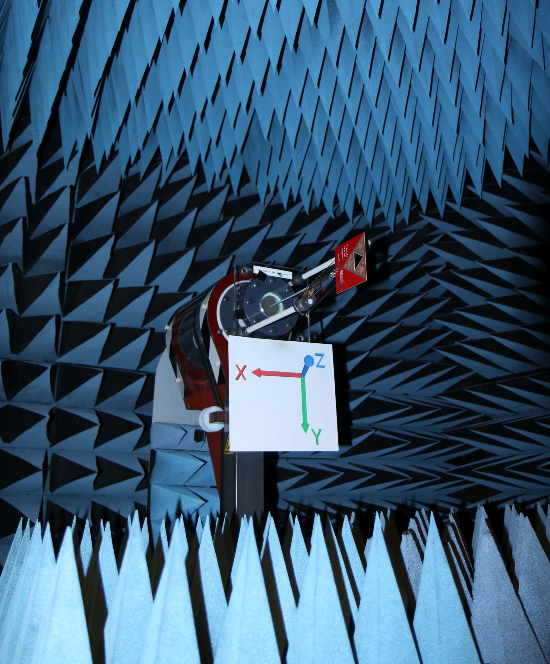
This antenna is fed by a standard “5-pin” PCB mounted right-angle SMA jack, oriented away from the back of the antenna as shown.
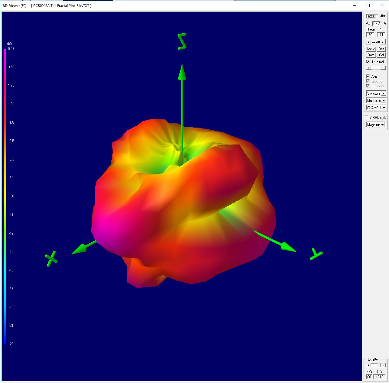
A full Excel spreadsheet 3D gain results report can be downloaded HERE. This extensive test program covers full 3D spherical gain patterns at 1671 stepped frequencies from 1300 MHz to 18 GHz in 10 MHz steps. The test report details higher level performance data, such as: Forward Gain, Peak Gain, Radiation Efficiency, and VSWR/Return-Loss vs Frequency.
The full set of 1671 spherical plot-files can be downloaded HERE in “zipped” format. Unzip and use this plot-file along with our downloadable 3D plotting software HERE. Then create rotate-able/scale-able 3D plots on your own desktop at any test frequency.
Please remember – We can test your antenna project too! We have a full range of testing services listed HERE

We hope you enjoy your sample antenna. We do not offer antenna design services here so that we may focus customer design confidentiality. These “biz card” antennas are just for fun, and they are not for sale.