- +1 919 200-0292
- info@antennatestlab.com

3D Printing Your Own Antennas
3D Printing Your Own Antennas
It Works, and You Can Do It!
What RF engineer or amateur radio enthusiast has not thought about 3D printing an antenna? It’s a natural combination of RF curiosity and and the power of 3D printing technology. You have probably even seen social media photos and posts about these antennas, but do these antennas even work? Has anyone properly tested them? Is it even practical with common materials and processes?
Download files for all 8 antennas: STL files are in THIS zipped archive, and SketchUp files are in THIS zipped archive (created with the free Sketchup Make 2017).
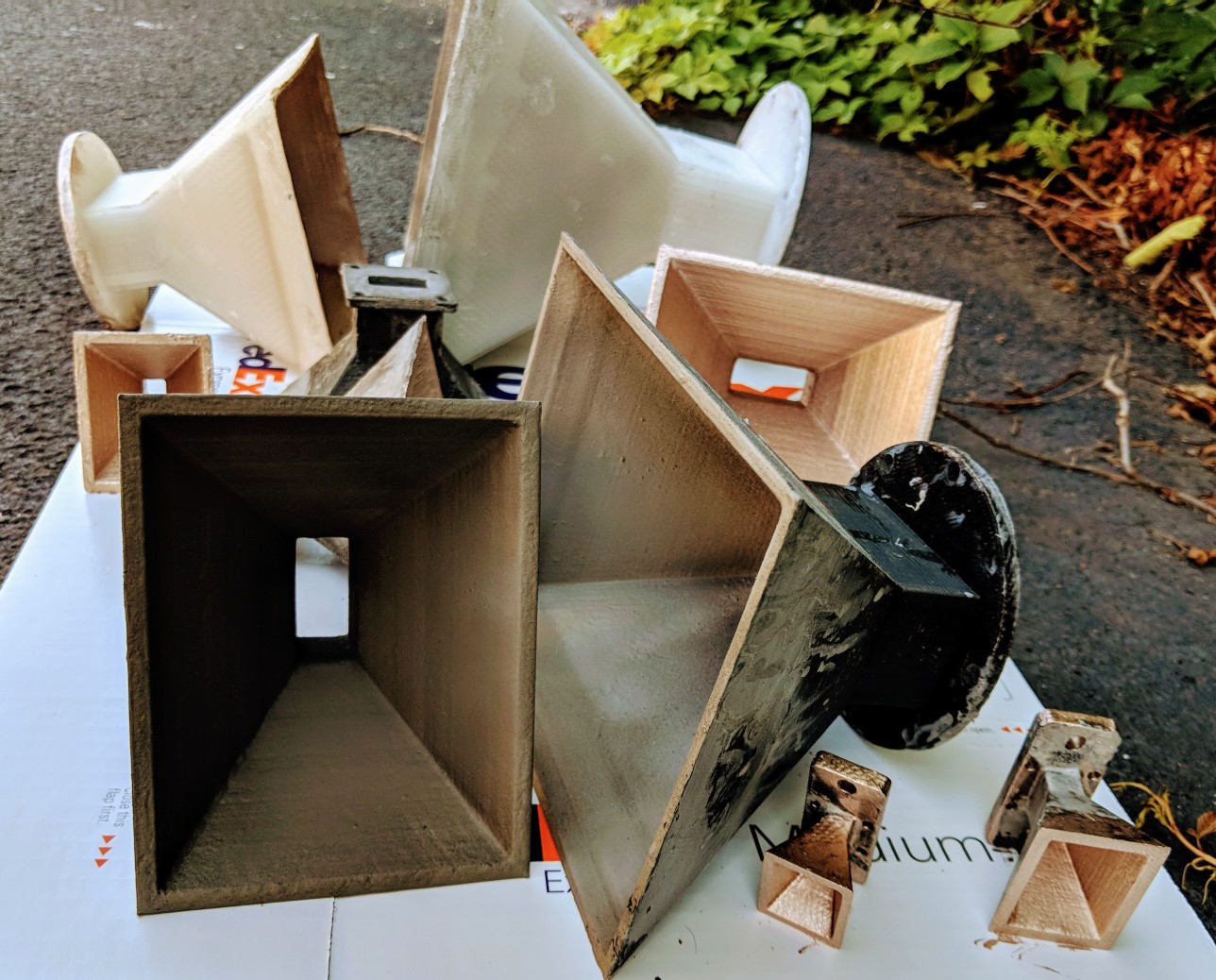
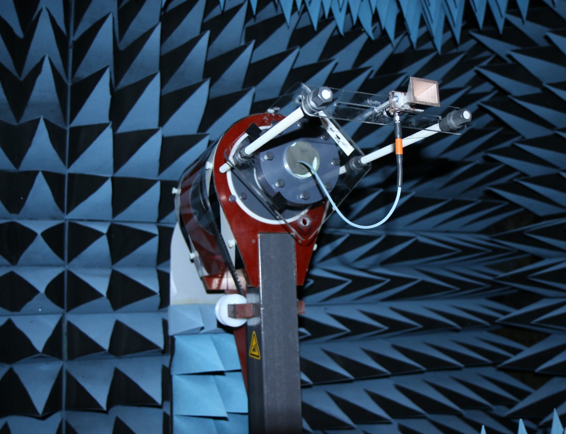
So we decided to give it a try ourselves, and also to add some value to the conversation. We are a professional antenna testing service with an RF anechoic chamber. We can build, optimize, and fully evaluate 3D antenna prints to answer these fundamental questions. In the end, it turned out to be quite practical, but not without a trashcan full or horns and lots of trial and error.
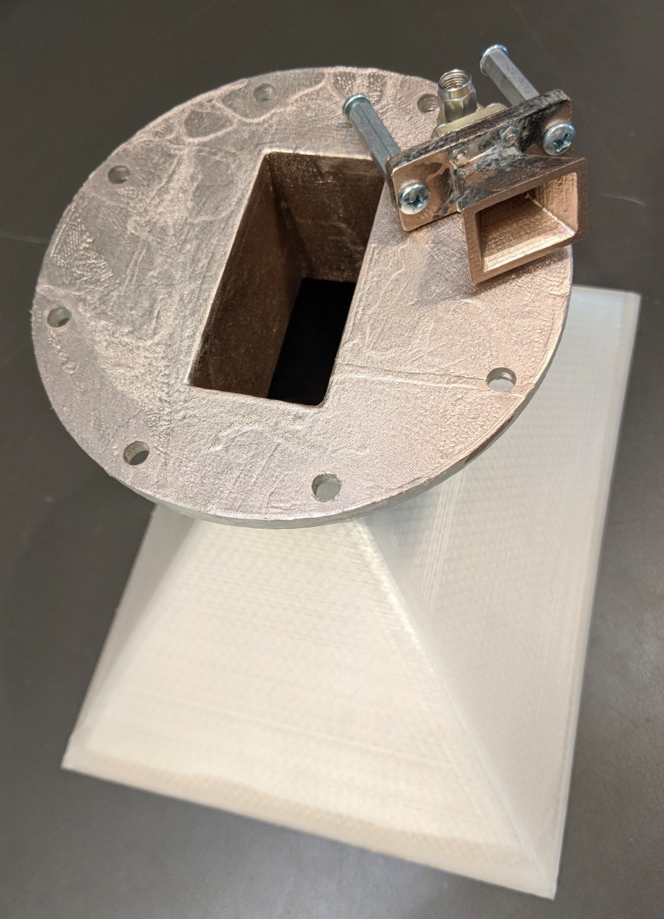
In the spirit of true science, we wanted to create plastic horns that could be tested against their commercial all-metal counterparts. So we chose to 3D print, metalize, and test the family of 15 dBi standard gain horns. Their simple rectangular horn shape design is decades old, and their standard geometries have very predictable gain. These “waveguide” horns have readily available coax launches (adapters) easily found surplus, purchased new, or even 3D printed. Despite their simplicity, commercial standard gain horns are expensive, normally priced from $500 to $1500. Contrast this to a spray metalized 3D print costing a dollar!
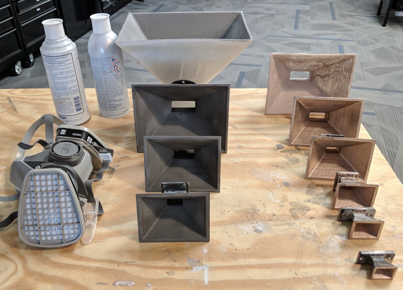
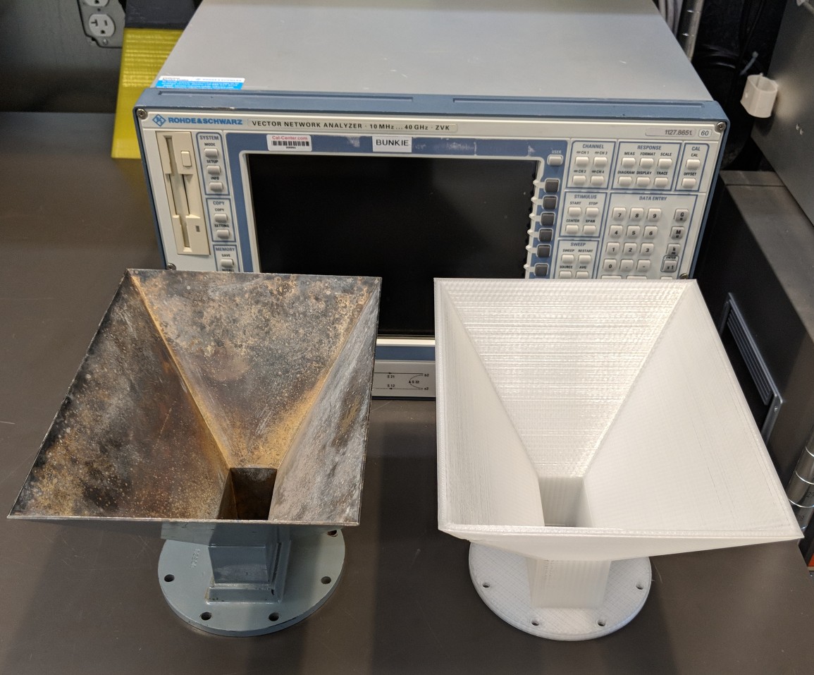
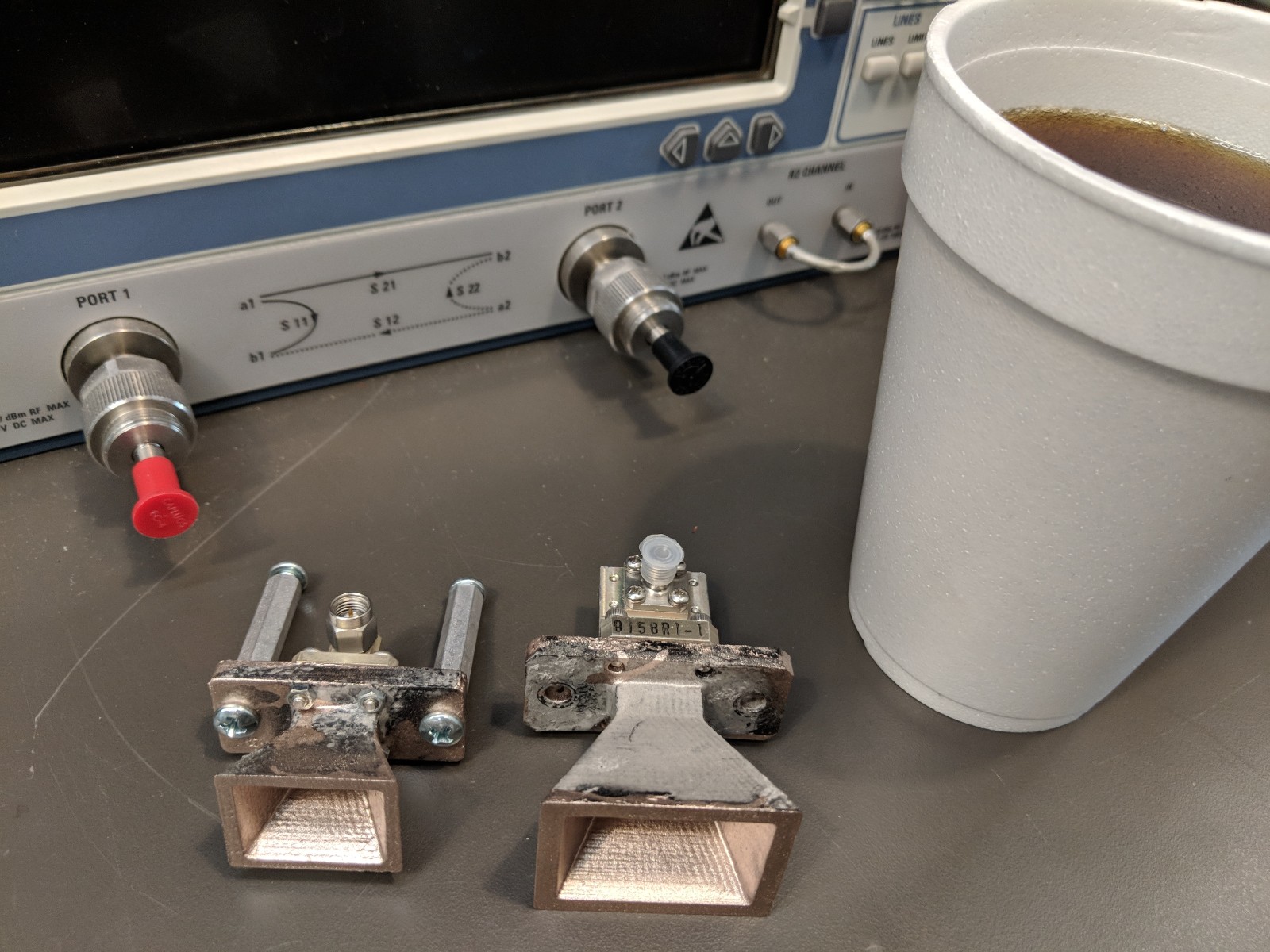
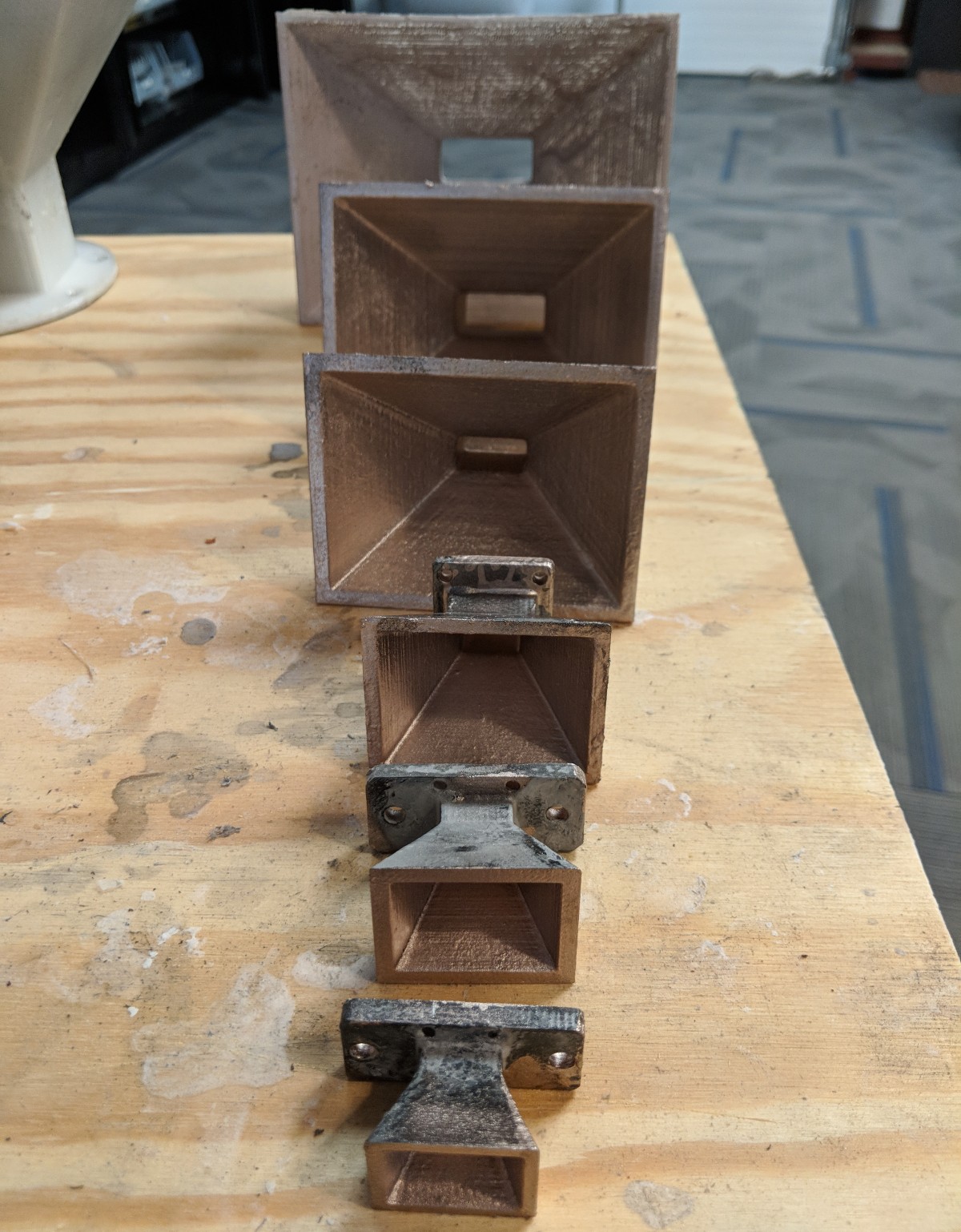
We limited our scope to the 2-40 GHz frequency range. This will entirely encompass the practical limits of common 3D filament printing. In the S Band (2-4 GHz), the standard gain 15 dBi horn is the size of a salad bowl, and required our large format printer. It could also be printed in parts and glued together from smaller prints. In the Ka band (26-40 GHz) the same 15 dBi horn will fit into the palm of your hand, and would challenge the tolerances of most typical 3D printers. Above 40 GHz, test equipment gets very expensive and parts get impractically small for casual experimenters.
Metalization
We chose MG Chemicals’ shielding spray paints for metalization because they are easy to buy (even on Amazon) and simple to use. Our first test antenna was an X band horn (8-12 GHz) with an easy to print 4 inch aperture. Two copies were printed to evaluate two common paints: “841 Super Shield™ Nickel” and “843AR Super Shield™ Silver Coated Copper”. Each was given two spray coats with drying time in between.
Disappointment !
The spec sheets for both paints showed impressive surface conductivity numbers and the metalized horns simply looked great! You can see the gain results in the horn shown in the left of Figure 3. We had high expectations. However, when patterned in the anechoic chamber, the results were terrible. Forward gain was only about 5 dBi, as opposed to the expected 15 dBi. But examining the test results showed that something was actually working. Both antennas had directivity of about 15 dB and the expected 30 degree beamwidths. Since return loss was “great” (> 20 dB), the only explanation was that the metalization’s realized surface conductivity was poor, causing the horns to suffer about 10 dB of internal loss.
Pre-Testing with VSWR
We devised a simple bench test to prove out this theory and to “pre test” antennas for this kind of loss. You should utilize this very useful approach, since not everyone has their own free-space antenna testing lab. Measuring the return loss (VSWR) of an antenna is the most common performance test (and does not require an anechoic chamber). The rule of thumb is that high return losses of more than 10 dB point to a “good” antenna. The thinking is that 90% or more of transmitted energy sent to the “good” antenna will radiate because it does not reflect back to the source. This is normally a useful test, when you can assume your antenna has small or zero losses. However a lossy antenna, or even a “dummy load” also has great return loss too!
Consider the low return loss from a short circuit. If you short a coaxial cable or the aperture of a low loss metal horn antenna, you can also expect a low return loss (large reflection). We verified these low return losses on “shorted” lab grade commercial horn antennas by covering their apertures with aluminum cooking foil. The same shorted aperture test on the 3D printed horns showed large (> 20 dB) return losses, indicating they were better attenuators than antennas!
In the figure below you can see that the “smoothed” surface antenna showed the desired low return losses. While there is some ripple due to the imperfect cooking foil “short” on the horn, the important thing to look for is some frequencies of low (approximately 1 dB) return loss. This could not happen if the inside surface of the antenna were lossy.
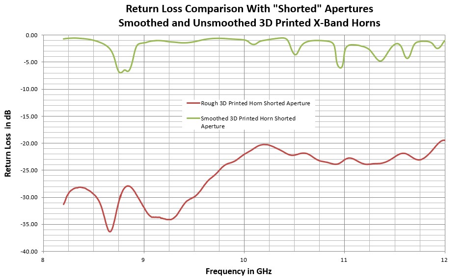
Despite the shiny appearance of the metalized paint, and the near-zero ohm meter resistance readings, surface resistance was the only possible loss mechanism. The tiny surface ripple artifacts of the 3D printing layers are small compared to the relatively large operating wavelength (1 inch at X Band). However, surface smoothing did eventually prove to be the key to removing this loss and achieving the target 15 dBi gain across the whole 2-40 GHz test range. But even applying multiple “liberal” coats of conductive paint did not sufficiently lower this loss without prior smoothing.
Surface Preparation
Sanding is an obvious way to smooth the 3D layer surface roughness. It works well, but it is time consuming. The horn’s funnel shape also creates triangular facets that are enclosed and tapered making power sanding tools impractical. After experimentation, we found that “solvent smoothing” was the most time effective and least effort. Acetone is a well known and useful solvent for ABS plastic prints, and it worked nicely on prints from our smaller ABS filament printer. Our large format printer only uses PLA filament, which did not seem to have a readily available solvent. However, a little research uncovered dichloromethane (methylene chloride) and a gallon was purchased on Amazon. It was highly effective at softening and smoothing the surface roughness on PLA plastic.
Chemical Safety
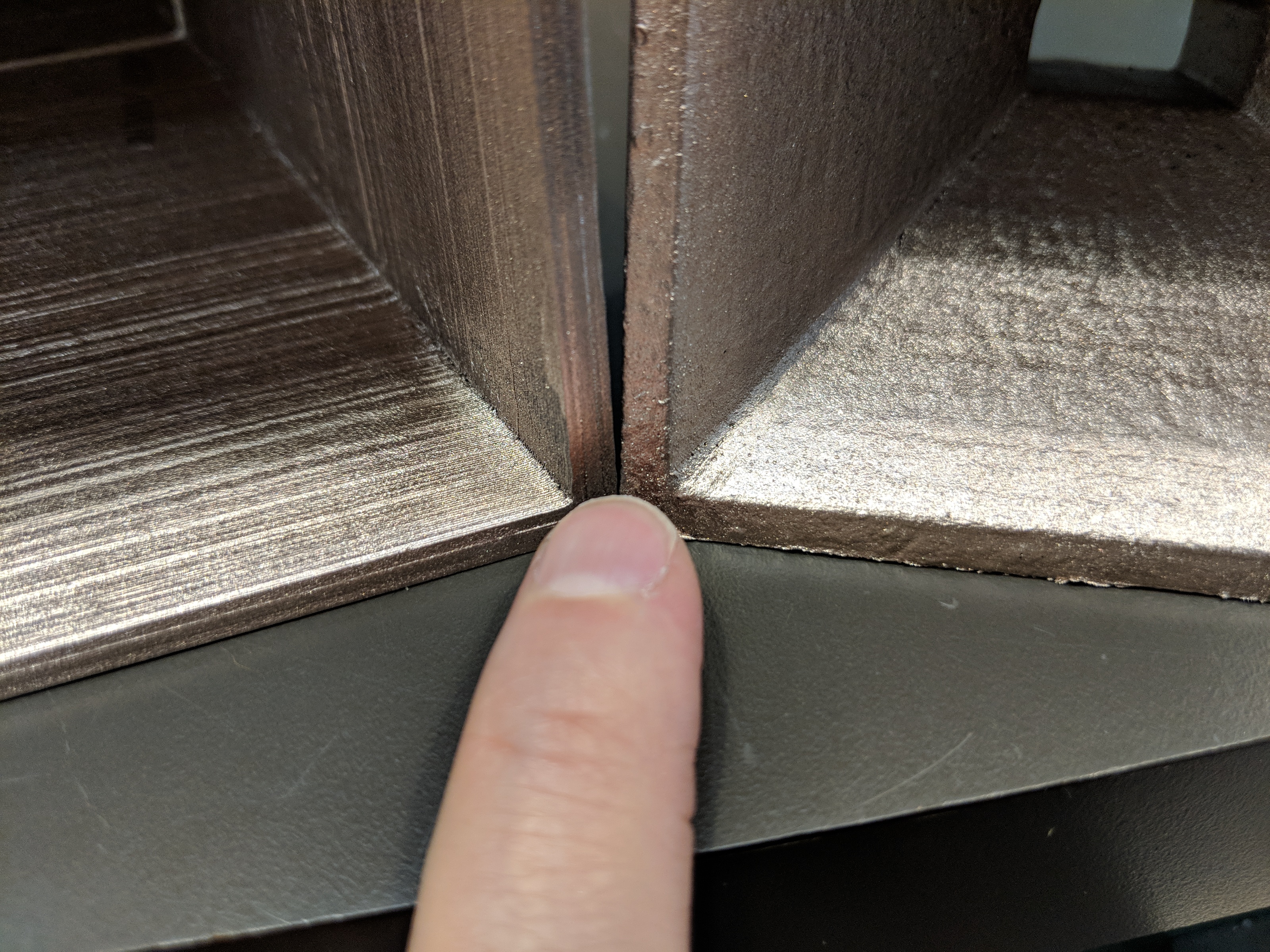
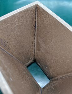
Both solvents are hazardous, but dichloromethane is especially poisonous. It has historically been the key ingredient in common paint stripper, but is being phased out due to its toxicity when used for DIY home projects. After some trial and error, we found the following process worked well. The resulting smoothed surface is shown in the right of the figure above.
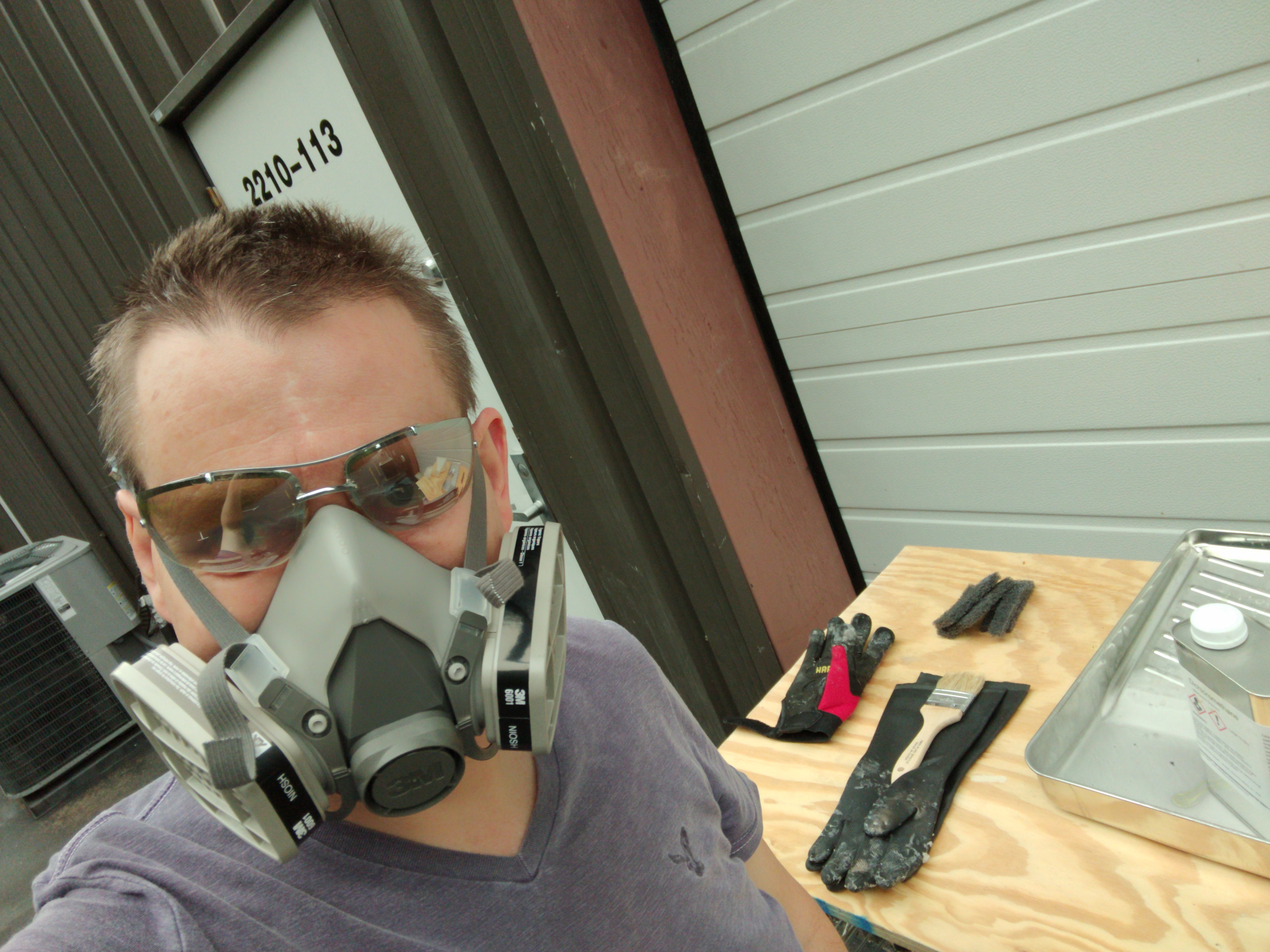
Work outdoors, since “adequate ventilation” is NOT practical indoors. You will still need a respirator mask that is rated for organic solvents (commonly available for “oil” based painting). Use full length chemical gloves that are specifically rated for your solvent, and protect these delicate chemical gloves by also wearing “work gloves” over top of them. You must also wear eye protection, since you WILL be splashing and brushing solvent.
Solvent Smoothing
We found it convenient to pour solvent into a common metal paint-roller tray and use this to brush on, scrub, and re-catch the solvent as in this figure. Disposable bristle brushes are best along with metal kitchen pot scrubbing pads. Don’t use plastic brushes or the green/blue plastic kitchen scrub pads, since the dichloromethane will soften them. It takes only a minute to smooth the inside of even the largest horn with the pot scrubber (or steel wool) if it is kept wet with solvent. A round bottle brush also easily scrubbed the waveguide portion of the horn. There is no need to smooth or metalize the outside of the horn, just work the inside surfaces and mating flange.
If you are assembling a larger antenna from smaller prints, now is the perfect time to “solvent weld” the already softened parts. Press and hold them together for about a minute while the solvent evaporates.
Applying the conductive spray paint is straightforward, proceed as you would spray paint any object. It is best done outdoors too, holding it in one hand with a glove allowing easy reorientation to get at all inside surfaces and the flange. Excess paint is simply shaken off. Two coats were always used and worked well.
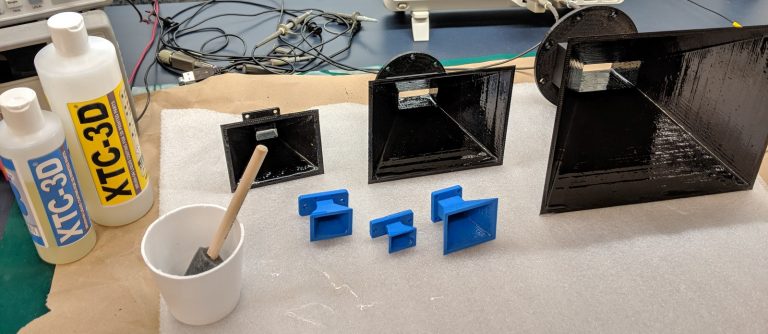
Epoxy Coating (Painting)
There is a second practical option available for surface smoothing. You can cover the rough 3D printed surface with a paint-on two-part epoxy coating. We tried “XTC-3D” from smooth-on.com, and it worked well for prints from 2 to 18 GHz. Some optional quick pre-sanding before application removes “large” high spots from rough surfaces. However, post sanding is not optional. The cured shiny surface looks great, but will not accept the metalized paint until lightly sanded. While less work than sanding smooth a rough 3D print, you will not be able to avoid this step. Any unsanded sections of “shiny” epoxy will not accept the metalization paint. We found inside corners to be problematic. In this photo, you can see blue plastic peeking through the conductive paint where the epoxy was not completely sanded. In horns from 18 to 40 GHz, the wave-guide features were just too small for the relatively thick coating. Critical dimensions were distorted, and holes and inside radiuses were starting to get filled in. However, antennas are quite tiny at these frequencies and you can smooth them quickly with small hobby files. There is really no need for solvent or epoxy coatings for antenans this small.
Metalized Coating Choices
The nickel version of the paint seemed to have several dB of loss at all frequencies despite surface smoothing. The chart below shows the nickel paint’s “performance hit” (surface loss) even in the S-band.
Luckily, the silver/copper version spray shielding paint worked well up to 26 GHz. But from 26 to 40 GHz the tiny Ka horn still displayed about 3 dB loss by having only 12 dBi of gain (even when solvent smoothed). This was easily solved by sanding the horn completely smooth with a tiny file, and repainting it. Since this Ka band horn is only an inch in size, its soft plastic walls were trivial to file smooth in just a minute. This extra smoothing step allowed it to display very low shorted aperture return loss on the bench and fully restored its expected 15 dBi gain in the chamber, as pictured above.
Conclusions
Yes, you can 3D print your own working microwave antennas using common materials and your “home-brewing” skills. Just smooth the active surfaces with solvent, sanding, epoxy, or filing then use our recommended conductive paint. If you can check the shorted aperture return loss / VSWR and verify that it has at least some frequencies of low return loss (less than 1 dB), you can reasonably expect the same antenna performance as a solid metal antenna. Complex shapes can be accommodated by splitting 3D prints into sections that allow for sanding/smoothing access before assembly by gluing or solvent welding. You can make various “cavity” electromagnetic parts like wave guides or coax-adapters this way. The conductive spray paint easily flows over and obscures surface sanding scratches and seams.
Results
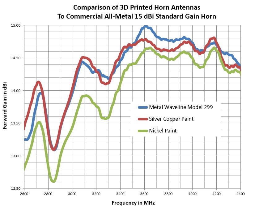
The graph above shows how good these horns can be. It compares a lab grade Waveline Model 299 Standard Gain Horn Antenna (15 dBi S Band model) and two 3D printed exact copies. The plastic versions were printed in PLA, solvent smoothed, and spray painted as described here. All three antennas were tested using the same Waveline Model 201NF Coax Adapter. The copper/silver painted 3D printed antenna’s gain was only +/- 0.2 dB different from the commercial horn antenna, well within measurement repeatability. The third curve on this graph shows the other identical printed antenna with two coats of the nickel based conductive coating. This formulation displays about 0.5 dB less gain, and gets worse by up to 5 dB at 10 GHz. The graph below shows the measured gain of our entire family of 15 dBi horns from 2 to 40 GHz, all hitting their gain targets.
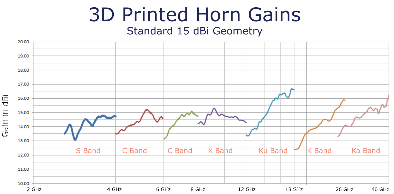
If you would like to experiment further, we have made the STL printable files available for download. All 3D designs were done with “SketchUp Make 2017”, a free 3D CAD design tool. The SketchUp files for these horns are also downloadable here if you would like to edit the geometries. Links are below …
Glossary & Terminology
- Standard Gain Horn: A waveguide rectangular horn antenna with predictable, precise gain and directivity, typically used as a reference antenna in anechoic chambers and antenna test ranges to calibrate and measure the performance of other antennas.
- Return Loss (VSWR): A measurement of how effectively RF power is delivered from a transmission line to a load (such as an antenna). While high return loss generally indicates a well-matched antenna, it does not account for power absorbed as heat by lossy materials in that antenna.
- Directivity vs. Gain: Directivity measures how concentrated an antenna’s radiation pattern is in a specific direction, independent of internal efficiency. Gain is directivity minus the internal losses of the antenna materials.
- Shorted Aperture Test: A diagnostic method where an antenna’s radiating opening is sealed with a conductive plane (like aluminum foil) to force total internal signal reflection. It is used to evaluate the attenuation (loss) of the horn antenna’s walls.
Frequently Asked Questions
Can I just apply thicker coats of conductive paint instead of smoothing the plastic? No, paint is too thin. At microwave frequencies, the structural ridges and valleys created by standard 3D printer layer lines cause severe surface impedance and phase scattering. Even with near-zero DC resistance, the RF skin depth follows the rough contour of the plastic. You cannot bridge these microscopic gaps purely with aerosol conductive paint; the underlying plastic must be chemically or mechanically leveled first.
Why does a poorly metalized printed antenna show excellent return loss on a network analyzer? A vector network analyzer measures what is reflected back to the source port. If the internal walls of the printed horn are highly resistive at RF frequencies, the forward traveling wave is absorbed as heat before it can radiate, and any reflected wave is absorbed again on the way back. The analyzer sees very little reflected energy and falsely reports a “perfect” impedance match, when in reality, the antenna is acting as a well matched attenuator (not an efficient radiator).
At what frequency does FDM dimensional accuracy become a bottleneck for printed antennas? Using standard FDM extrusion (0.4mm nozzle, 0.1mm–0.2mm layer heights), dimensional tolerances begin heavily impacting performance above 18 GHz (K and Ka bands). At these frequencies, the waveguide apertures and feed points are small enough that typical print variances or the thickness of an applied epoxy coating will actively detune the antenna, necessitating high-resolution resin printing or manual filing for accurate geometry. Parts are best smoothed and given final dimensions with small hand held files.