- +1 919 200-0292
- info@antennatestlab.com

The 3D Spherical Coordinate System
The 3D Spherical Coordinate System
Understanding Spherical Coordinates
Antenna Test Lab Co performs 3D spherical evaluations using Phi axis (roll) and Theta (turntable) stepping per the “Great Circle Cut System”. This sometimes called an “Elevation over Azimuth” or “Az/El” system. This way, native results are available directly in the standard preferred spherical coordinate system.
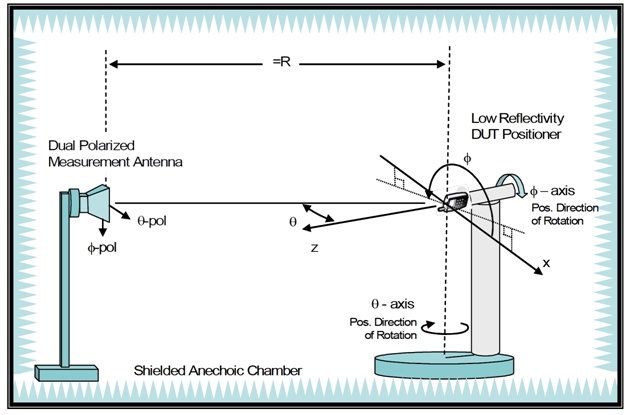
This enlargeable diagram shows the Theta axis (turntable or azimuth control) with the Phi axis “roll positioner” (or elevation control) on top of it. Our positioners are fiber-optically controlled, and made of all plastic materials so as not to absorb RF energy. The rate of turn is 3 RPM (20 seconds) with a positioning accuracy of better than 1 degree. Photos of the laboratory show sample mounting arrangements for various customer antennas. The ATL chamber antennas can cover 300 MHz to 40 GHz. For increased throughput speed, we use three-port VNA measurements and quad ridge horns to simultaneously take vertical and horizontal polarized antenna gain measurements.

Measurements are logged in Excel workbook tables of Theta and Phi spherical coordinates, per IEEE Standard 149-2021, “Test Procedures for Antennas”. The standard IEEE antenna coordinate system is illustrated below. The spherical coordinates relate to the Cartesian axes as shown in this click-to-enlarge diagram.
Evaluate Your Antenna
Ready to find out more about your antenna … partner with an antenna evaluation company and never be “in the dark” again! Contact us here.
Glossary & Terminology
- Great Circle Cut System: A rolling head over turntable mechanical method of measuring 3D antenna patterns by taking multiple 2D planar cuts around a sphere, utilizing an azimuth turntable (Theta) and a roll positioner (Phi).
- Quad-Ridge Horn: A specialized, directional wideband antenna featuring four internal conductive ridges. It is uniquely capable of transmitting or receiving two orthogonal polarizations (vertical and horizontal) simultaneously from the same point (phase center) in space.
- Spatial Accuracy: The mechanical precision of the turntable system (e.g., within 1 degrees), ensuring the VNA records data at the exact intended physical angle to yield a true representation of the radiation pattern.
- IEEE Std 149-2021: The recognized industry-standard document defining the required procedures, terminology, and coordinate systems for measuring, analyzing, and reporting antenna performance.
Frequently Asked Questions
Why use dielectric (fiberglass and plastic) positioners and fiber-optic controls instead of standard motorized turntables? Standard metal turntables and copper control cables reflect and absorb RF energy, whose reflections corrupt the radiation pattern of the antenna being tested. Using all-plastic components and optical fibers keeps the measurement environment electromagnetically “invisible,” ensuring the instrumentation only records the true performance of the device under test.
How does the lab capture both horizontal and vertical polarizations without doubling the test time? We utilize three ports of a 4-port Vector Network Analyzer connected to a dual-polarized quad-ridge chamber horn antenna. This specific hardware configuration allows the test system to sweep, measure, and record both the vertical and horizontal polarization vectors simultaneously during a single mechanical position of the turntable.
Why is the Great Circle Cut method preferred over other spherical measurement techniques? The Great Circle Cut natively produces test data in the exact Theta/Phi spherical coordinate format required by IEEE Std 149-2021. This provides engineers with clean, standardized data tables that can be immediately imported into structural CAD or electromagnetic simulation software without requiring messy, error-prone coordinate transformations.