- +1 919 200-0292
- info@antennatestlab.com


About Us
About Us
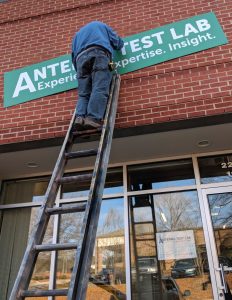
Antenna Test Lab Company operates a dedicated commercial antenna testing facility located in the Research Triangle Park (RTP) region of North Carolina. Founded in 2001, our laboratory provides independent, highly accurate RF testing services to a broad spectrum of industries. We focus on delivering straightforward, empirical performance insights directly to antenna hardware engineers, RF designers, and project managers, bypassing marketing noise to focus purely on verifiable data and practical hardware solutions.
Our Lab
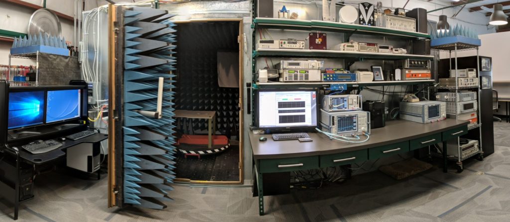
Our primary testing environment features a fully anechoic chamber equipped with a fast spherical two-axis all-dielectric positioner and ultra-broadband custom reference antennas. This controlled facility allows us to characterize antenna performance from 300 MHz to 40 GHz with high repeatability and minimal multipath interference. The laboratory is flexible enough to handle highly diverse physical and RF requirements, ranging from the evaluation of compact WiFi and BLE trace antennas for IoT startups to qualifying mission-critical satellite hardware—including antenna systems currently deployed on the lunar surface.
How We Operate
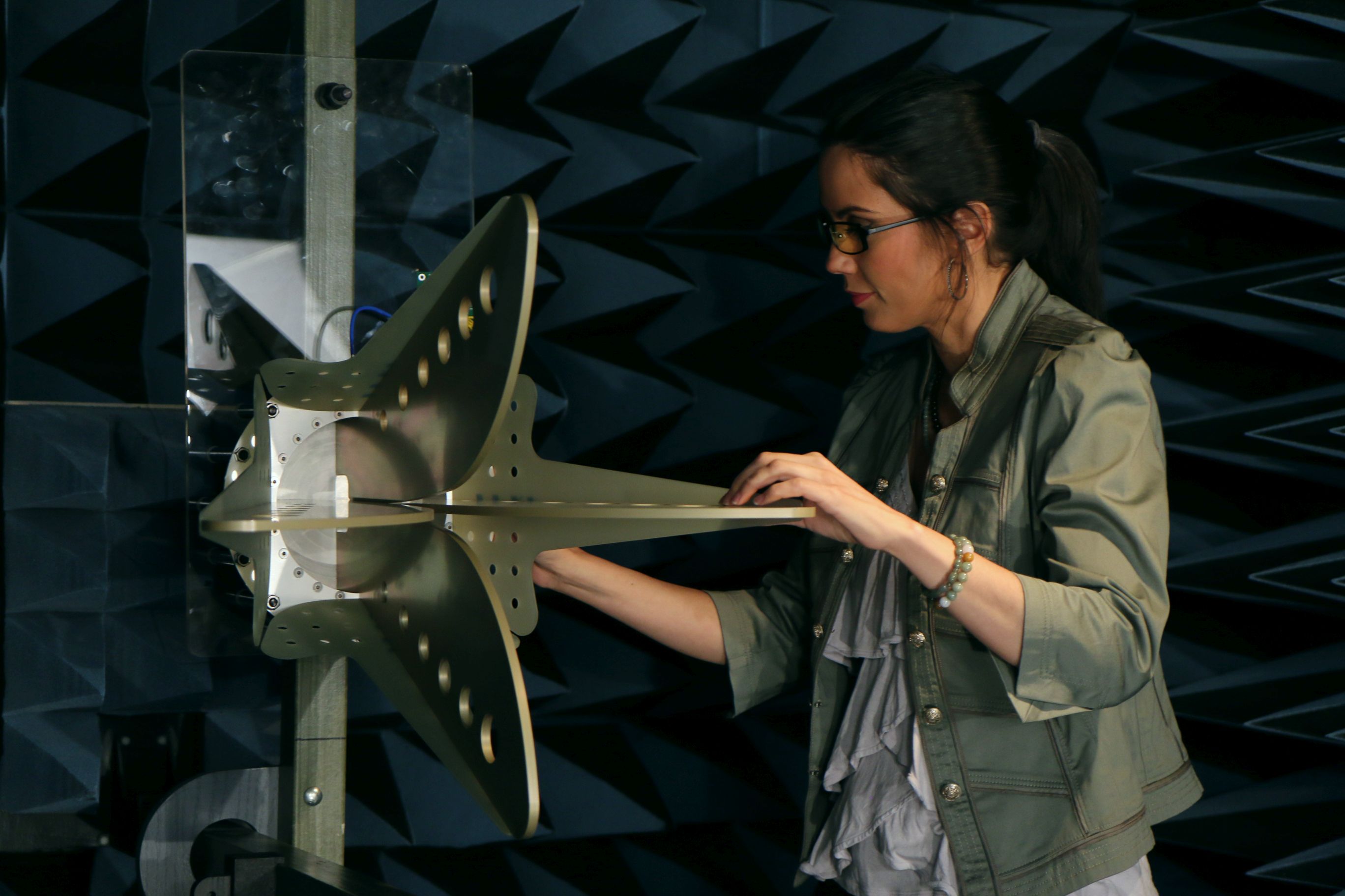
To expedite your engineering workflow, our evaluation and reporting methodology follows a straightforward repeatable sequence. Turn around time is often just two days.
- Phase 1: Quick Custom Quotations – negotiated directly with a RF engineer based on posted prices. This ensures every customer receives a time and cost optimized test plan.
- Phase 2: Physical Setup and Alignment – The device under test (DUT) is securely mounted to our two-axis positioner, drawing from a library of over 100 custom mounting brackets. Then the appropriate ultra-broadband horn is configured and calibrated for the specific frequency bands of interest.
- Phase 3: Vector Data Acquisition – Our system sweeps the customer antenna to capture full vector gain data across the specified frequency range. This enables comprehensive evaluation of either linearly or circularly polarized antennas, specifically measuring Left-Hand Circular Polarization (LHCP), Right-Hand Circular Polarization (RHCP), and axial ratios.
- Phase 4: Data Processing and Handoff – Rather than locking test results behind proprietary software viewers, we process and deliver all measurement data in standard Excel spreadsheets. These files include raw numerical data alongside interactive 3D plots, allowing engineering teams to easily ingest the data into their own RF simulation or system analysis tools. Customers can render interactive polar of spherical plots in their browser screen with no downloaded software. Data may be emailed or uploaded to your ITAR approved portal.
Who and Where We Are
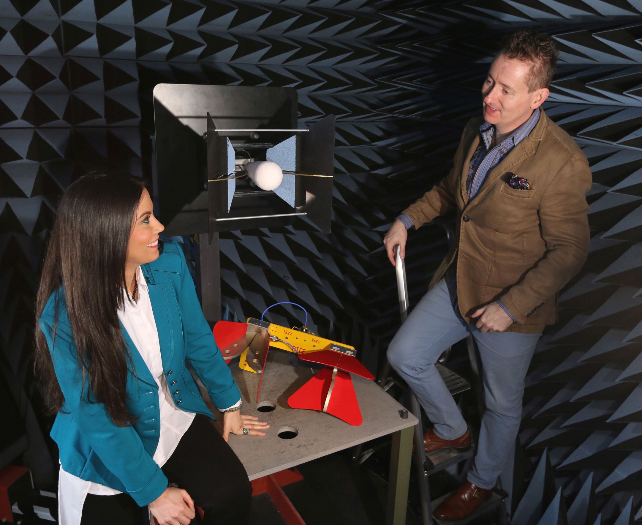
As a testing facility managed by an antenna engineer with over 35 years of specialized RF experience, we operate on a principle of technical transparency. Customers communicate directly with the engineer conducting their tests, ensuring that the nuanced performance characteristics, operational benefits, and physical limitations of their antenna are thoroughly understood. We also maintain an open-door policy at our North Carolina facility, actively encouraging hardware teams to visit the lab and observe the antenna testing process firsthand. Contact Us.
Glossary & Terminology
- Anechoic Chamber: A shielded testing room completely lined with radio-wave absorbing material. It is designed to eliminate internal signal reflections (multipath) and external RF noise, simulating a true free-space environment for accurate baseline RF field measurements.
- Axial Ratio: A parameter used to quantify the circular uniformity of a circularly polarized antenna, representing the ratio of orthogonal components of the electric field. A theoretically perfect circularly polarized antenna has an axial ratio of 0 dB (meaning it has constant gain at any vertical or horizontal angle).
- Vector Gain: A comprehensive measurement that captures both the amplitude (magnitude) and phase of an antenna’s radiation pattern. This is required for determining complex polarization characteristics. Used for BOTH linearly and circularly polarized antennas.
- Reference Antenna: A gain calibrated antenna by which other antennas are measured against.
- LHCP / RHCP (Left-Hand / Right-Hand Circular Polarization): Classifications of circular polarization that describe the direction the electric field vector rotates (counter-clockwise or clockwise, respectively) as the radio wave propagates through space.
Frequently Asked Questions
What file format do you use to deliver antenna pattern and gain data? We deliver all measurement data in standard, non-proprietary Microsoft Excel formats. You can find downloadable examples here. The deliverables include the raw data arrays alongside interactive 3D spherical or 2D polar plots. This ensures you do not need to purchase or install specialized software to view, analyze, or present your results.
What is the maximum frequency range your lab can support? Our test chamber and instrumentation are equipped to measure antenna performance across a wide spectrum, from 300 MHz to 40 GHz. This allows us to test everything from sub-GHz ISM bands to high-frequency millimeter-wave (mmWave) applications. Standard frequency sweeps are normally 201 up to 401 steps.
Can you accurately characterize circularly polarized antennas? Yes. Because we capture full vector gain data during our automated sweeps, we fully characterize circularly polarized antennas. We provide precise measurements for both LHCP and RHCP gains, as well as axial ratio variations over all frequencies and pattern angles.
Can our engineering team observe the testing in person? Absolutely. We welcome hardware and RF teams to visit our facility in Research Triangle Park, NC. Visiting allows you to observe the testing procedure, verify the physical test setup of your hardware, and discuss the results in real-time with our principal RF engineer.