- +1 919 200-0292
- info@antennatestlab.com

Measuring Passive Antenna Gain (dBi)
Measuring Passive Antenna Gain (dBi)
How We Measure Your Antenna’s Gain and Radiation Pattern
The standard method for quantifying antenna performance is Gain. An antenna’s gain is so fundamental to its evaluation, that we have written several tutorials on the subject in our educational section. Gain is a function of direction, meaning that gain is usually different in various directions. Varying gains in different directions, create an antenna gain pattern, or radiation pattern. This pattern tells us the preferred, or best directions, for energy from your antenna. Oh, and it tells us its poor directions too!
Chamber Configuration
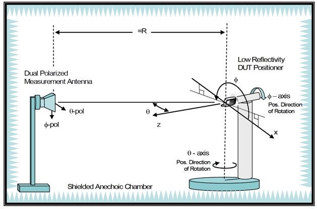
We test gain by illuminating your antenna with a frequency swept RF signal from one of our anechoic chamber “source antennas”. Then we measure your antenna’s gain (in dB isotropic or dBi) via the substitution method. The substitution method involves setting up our calibrated laboratory reference antenna over a radiated path across the chamber, then normalizing (or “zeroing”) that path loss to 0 dB.
The Substitution Method for Gain Measurement
Then we substitute your antenna in place of our reference antenna, and re-measure the change in path loss. By simply adding our reference antenna’s calibrated gain (in dBi) to the change in path loss, we determine your antenna gain in dBi. In other words, your antenna’s gain is measured relative to our standard antenna. Our inventory of reference antennas are chosen to span wide frequency ranges. For example, using our calibrated 300 MHz to 30 GHz reference horn allows us to measure your antenna’s gain over its entire operating range, in hundreds of physical directions, in one test run. Tests DO NOT have to be repeated at each individual frequency, as with tuned dipole substitution.
Real-World Limitations: The Dipole Pattern Example
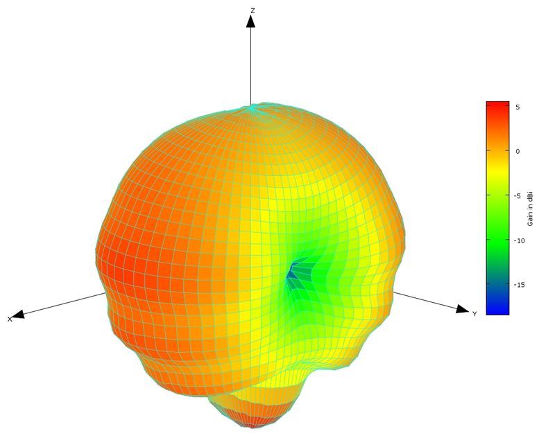
Patterning this expensive laboratory-grade reference dipole in three dimensions clearly reveals the imperfections inherent in real-world antenna deployment. While theoretical models depict a perfect, symmetrical “doughnut” radiation pattern for a dipole, measured 3D spherical patterns often show significant distortion along the -Z axis. When captured in high-resolution (5-degree increments), these measurements expose pattern deformation caused by feed line radiation and signal scattering from the attached coaxial cable. This occurs despite the presence of sophisticated tunable balun specifically designed to decouple the feed line.
The Importance of Full Spherical Evaluation
Identifying feed line radiation and pattern distortion requires comprehensive 3D testing environments completely free of blind spots. For instance, testing a dipole in a standard “Satimo” type arch might miss crucial Z-axis anomalies because the feed line radiation falls directly into the chamber’s physical blind spot at the base of the arch. Discovering these hidden anomalies illustrates why it is a dangerous misconception to assume a real-world dipole exhibits exactly 2.14 dBi of gain in its primary lobes. Finding even a few physical directions that perfectly hit that 2.14 dBi mark is rare, highlighting the strict necessity of full spherical evaluations to understand an antenna’s true operational behavior.
Next Steps
Find out how a partner antenna test company can help you … Contact Us Here
Glossary & Terminology
- Anechoic Chamber: A specialized testing environment lined with RF-absorbing material designed to suppress reflections of electromagnetic waves. This simulates an infinite free-space environment without apparent walls, floor, or ceiling. Allowing for highly accurate antenna pattern measurements without multipath reflection interference.
- Balun (Balanced to Unbalanced): A passive electrical device used to interface a balanced load (like a dipole antenna) to an unbalanced feed line (like a coaxial cable). Its primary function in antenna testing is to prevent common-mode RF currents from traveling along the outside of the coax shield, which radiate and distort the pattern.
- Isotropic Radiator (dBi): A theoretical point-source antenna that radiates RF energy perfectly equally in all directions (a perfect sphere). Gain expressed in “dBi” measures how much an antenna’s directional radiation concentrates energy compared to this theoretical, loss-less isotropic baseline.
- Substitution Method: A standard RF test procedure where the unknown gain of an antenna is determined by comparing its received or transmitted signal strength to that of a calibrated reference antenna under physically identical test conditions.
Frequently Asked Questions
How does the substitution method account for cable and connector losses during a frequency sweep? By normalizing the initial test path using a calibrated reference antenna, the substitution method inherently zeroes out the static losses of the test environment. This includes the source cables, the receiving cables, connector insertion loss, and the free-space path loss of the chamber itself. As long as the physical cables connecting to the Device Under Test (DUT) remain identical to those used with the reference antenna during calibration, those environmental losses are mathematically canceled out of the final dBi calculation.
Why use a broadband reference horn instead of tuned reference dipoles for chamber calibration? Tuned dipoles offer excellent accuracy at very specific, narrow frequencies, but they require physical adjustment (tuning the element and balun-arm lengths) for every single frequency point of interest. A calibrated broadband horn provides a known, stable gain profile across a massive bandwidth (ours is 300 MHz to 30 GHz). This allows engineers to run continuous, automated frequency sweeps without breaking down the test setup or opening the chamber doors.
Can feed line radiation be completely eliminated during 3D pattern measurements? In practical applications, completely eliminating feed line radiation is extremely difficult, especially at lower frequencies. While high-quality tunable baluns, ferrite chokes, and careful cable routing significantly attenuate common-mode currents on the coax shield, some residual radiation usually persists. This physical reality underscores the importance of full spherical 3D testing, as it measures and accounts for the actual impact of the feed line on the antenna’s final, deployed radiation pattern.