- +1 919 200-0292
- info@antennatestlab.com


1D vs. 2D vs. 3D vs. 4 Dimensional Patterns
1D vs. 2D vs. 3D vs. 4 Dimensional Patterns
How To Choose Your Antenna Pattern Type
Deciding to characterize an antenna’s radiation pattern provides critical baseline data for system performance and application suitability. The immediate engineering decision becomes whether to specify traditional two-dimensional polar plots or comprehensive three-dimensional spherical plots. The optimal choice depends entirely on the antenna’s physical geometry, its expected radiation behavior, and the maturity of the design.
Traditional 2D polar plotting remains highly effective for antennas with established, predictable behaviors. Engineers typically specify 2D cuts for directional antennas or those exhibiting high structural symmetry, where the radiation characteristics in the principal planes (E-plane and H-plane) provide sufficient performance data. This approach is highly efficient and yields actionable data when the antenna’s baseline performance is already well documented and understood.
Conversely, 3D spherical patterning is essential for omnidirectional antennas, newly prototyped designs, or completely uncharacterized radiating elements. A full spherical capture ensures that unpredictable pattern disturbances—often caused by feed line coupling, enclosure proximity, or PCB ground plane edge diffractions—are fully identified. For most modern development cycles, 3D profiling is the recommended standard because it captures off-axis anomalies and structural interactions that a standard 2D slice will easily miss.
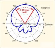
2D Polar Plots |
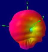
3D Spherical Plots |
|---|---|
 |
 |
Higher angular resolution (detail), but only in the chosen “cuts” (usually Elevation/Azimuth or E&H Plane) |
Lower resolution, but spread over the entire radiation sphere |
Reveals sharp peaks and nulls in highly directional or microwave antennas, missing details outside of the prime measurement planes |
Reveals distortions and unexpected pattern effects, nothing is missed by exploring the entire sphere |
Cannot calculate radiation efficiency, since the entire sphere is not explored |
Customers receive a spherical integration of their 3D patterns, which we present as a radiation efficiency vs. frequency graph |
2D Is Best Suited For These Types Of Antennas: |
3D Is Best Suited For These Types Of Antennas: |
Horns, Yagi’s, Log Periodics, Monopoles, Patches |
Any PCB mounted/soldered device, PIFA, Loops, Zig-Zags, Coils, “Chip Antennas”, SMT/SMD |
High gain (directional), Microwave |
Virtually all embedded antennas, omni-directional antennas, any antenna with suspected or unknown feedline interaction (i.e. no balun) |
Ultimately, the best way to decide which pattern type is best for you is to Contact Us with your antenna test goals. We will help you decide which additional measurements are crucial for your application, like efficiency, front-to-back ratio, front-to-rear ratio, peak gain, or circularly polarized parameters like LHCP/RHCP gain or axial ratio.
Glossary & Terminology
- Polar Plot: A two-dimensional graph depicting the radiation pattern of an antenna in a single plane, showing relative field strength or gain as a function of the angle.
- Spherical Pattern: A comprehensive three-dimensional representation of an antenna’s radiation characteristics, capturing performance data in all directions over a complete sphere surrounding the device under test.
- Swept Frequency: A testing methodology where a network analyzer or signal generator continuously varies its output frequency across a defined bandwidth to characterize how an antenna’s response changes over that spectrum.
- Feed Line Interaction: Unintended electromagnetic coupling between the radiating antenna structure and the transmission line supplying its RF power, which often distorts the intended radiation pattern.
Frequently Asked Questions
Can a 2D polar plot accurately represent a newly designed PCB trace antenna? Generally, no. Because PCB trace antennas are heavily influenced by the board substrate, nearby components, and asymmetrical ground planes, a 2D slice will likely miss critical nulls or unintended cross-polarization effects. A 3D spherical measurement is necessary to fully map its real-world performance.
How does the physical enclosure affect the choice of pattern testing? Enclosures—especially those with metallic paints, irregular shapes, or closely spaced conductive structural elements—introduce reflections, diffractions, and detuning. 3D patterning is highly recommended when testing an antenna inside its final housing, as these interactions routinely cause unpredictable, off-axis radiation disturbances.
How do I determine the appropriate angular step size for a 3D spherical measurement? The required angular resolution depends directly on the electrical size of the antenna and its expected directivity. High-gain, highly directional antennas with narrow beamwidths require fine step sizes (often 1 degree or less) to accurately capture sharp nulls and the exact peak of the main lobe. For electrically small, low-gain omnidirectional antennas, a coarser step size (such as 5 to 10 degrees) is usually sufficient to capture the overall pattern shape while significantly reducing chamber testing time. Just contact us and we can discuss it.