- Home
- Services
- Prices
- Education
- 3D Plotting Software
- Published Articles
- Consumer Antennas
- 3D Printing Antennas
- Educational Overview
- Our Tutorials
- Sample Test Reports
- Examples Overview
- Gallery
- Biz Card Antennas
- 3D Printing Antennas
- Example 1 Embedded Cellular
- Example 2 PCB LPDAs
- Example 3 RFSPACE
- Example 4 RHCP Spiral
- Example 5 Corrugated Horn
- Example 6 CP Omni Antenna
- Example 7 Palm Tree
- Example 8 Patch Array
- Example 9 Ka Band Horn
- Example 10 Eggbeater
- Example 11: Log Spiral
- Example 12: Raspberry Pi
- Example 13: Radar Modules
- Example 14: UWB Spiral
- Example 15: Dual Pol Vivaldi
- Biz Card Antennas
- RFSPACE Brand Antennas
- Helium Antenna Reviews
- Silly Antennas
- About Us
- Contact Us
- Quotes
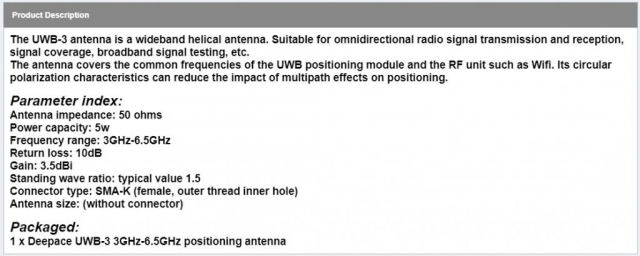
This example page showcases our circularly polarized antenna testing with swept frequency 3D patterns and a 4D gain vs frequency animation video.
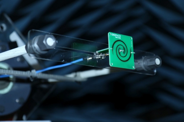
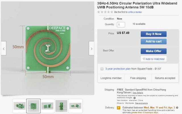
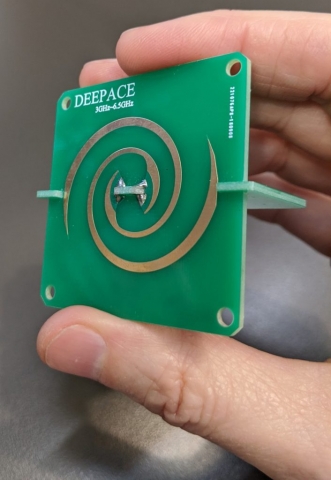
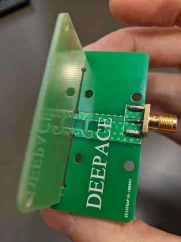
The antenna was purchased on eBay for $7.49 and shipped directly from China. The basic specifications were simply listed as 3 to 6.5 GHz with a gain of 3.5 dBi circularly polarized. The PCB is branded DEEPACE.
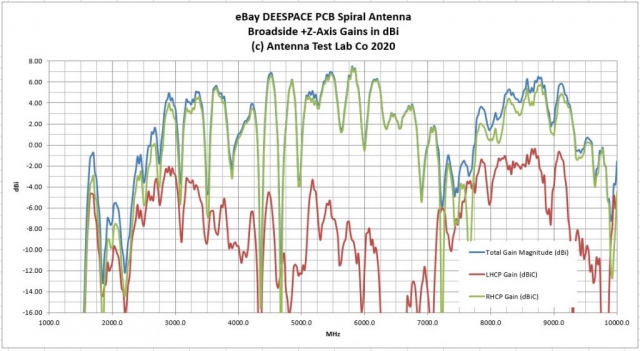
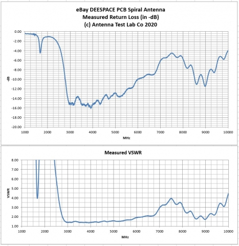
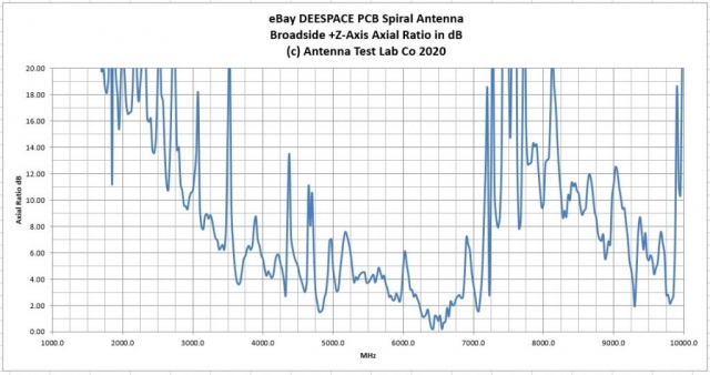
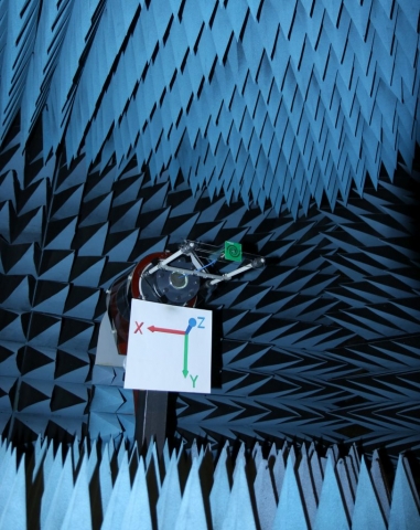
We 3D patterned the antenna over a test frequency range of 1.5 to 10 GHz and linked all of the results and test data below. The broadside RHCP gain of the antenna (Z axis in our setup) varied wildly from +7 to -20 dBi over the UWB operating range of 3 to 6.5 GHz. There are 500 MHz segments in the operating band that exhibited 20 dB of gain variation, which would be ill suited for UWB communications requiring flat distortionless signals.
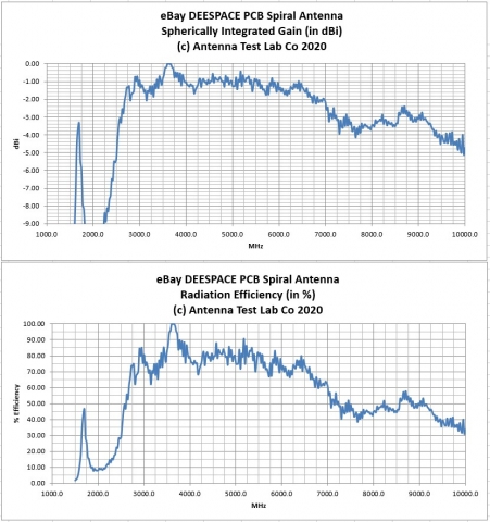
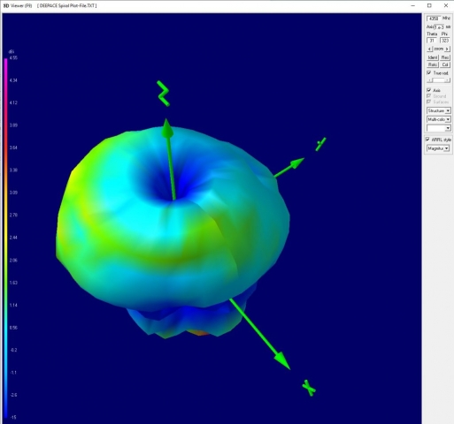
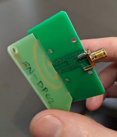
Overall, radiation efficiency was good and off axis RHCP gain was much flatter than “broadside”. Our 4-dimensional gain graph below (frequency swept 3D gain animation) tells this story. You can see nulls developing in the main axis at frequencies like 4350 MHz. This is probably due to the reward spiral radiation reflecting off of the balun PCB on the back of the antenna assembly. However, this is still a fun hobbyist RHCP UWB microwave antenna for only a few dollars.
Our vector gain (with circularly polarized gain break out) data in Excel format can be downloaded HERE.
The 3D plot-file may be downloaded HERE and used with our 3D Plotting Software.
Date 06 Apr, 2020
Categories 3D Spherical Patterns, ALL Antennas, Circularly Polarized, EIRP Radiation, Microwave, PCB
(c) Copyright Antenna Test Lab Company 2023


