- +1 919 200-0292
- info@antennatestlab.com

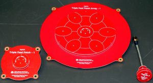
Example 8: Triple Feed Patch Array CP Antenna
This sample report features a directional circularly polarized antenna, evaluated with our 3D spherical patterns at high resolution (5 degree steps). The antenna was swept from 5300 to 6300 MHz.
Background: This antenna is the work of Maarten Baert . It is an array of Triple Feed Patches. First the Triple Feed Patch. The designer’s vision is: “The (center) patch has three feed pins that are fed with a 0°, 120° and 240° signal. All other circularly polarized patch designs that I’m aware of either use a single feed pin and an asymmetric patch to create circular polarization, or they use two feed pins that are 90° out of phase. Both methods introduce asymmetry in the radiation pattern, whereas the three-phase feed method doesn’t. That’s why we chose that name. ” Secondly, the circular array of patches. The designer’s vision is: “It’s an unusual array design, the patches have different shapes and only the one in the center is fed. The other ones are weakly coupled with the center patch as well as each other in order to make them resonate in phase with the center patch. The goal was to minimize FR4 losses by keeping the feed lines very short, while also keeping the amplitude of the center patch somewhat higher than the surrounding patches in order to reduce sidelobes. The resulting radiation pattern has a lower peak gain (about 15 dB instead of the theoretical 17.5 dB), but the main lobe is a lot wider and contains more energy overall (since less energy is lost in sidelobes).”
Results: The test results show that the design is sound and Maarten Baert has met his design goals. The Triple Feed Patch: Gain is +9.3 dBi with an axial ratio of 0.5 dB. Radiation efficiency is approximately 75% (from an average gain of -1.5 dBi). The Triple Feed Patch Array: Gain is +14 dBi with an axial ratio of 0.5 dB. Radiation efficiency is approximately 75% (from an average gain of -1.5 dBi). Both antennas are excellent performers and are innovatively designed, especially considering they operate at 5.8 GHz on inexpensive FR4 PCB. These are our 5-degree resolution spherical patterns, and each antenna has over 1.2 million gain measurements! Our test report includes graphs of gains (RHCP, LHCP, and magnitude) vs frequency, as well as our interactive variable frequency polar plots. As always, all data is provided in Excel spreadsheet format, allowing for additional plots and post-analysis. The results spreadsheet can be downloaded HERE.


Date 14 Apr, 2018
Categories 3D Spherical Patterns, ALL Antennas, Circularly Polarized, Microwave, PCB