- +1 919 200-0292
- info@antennatestlab.com


What is an Anechoic Chamber?
What is an Anechoic Chamber?
The Basics
“Anechoic” (an·echo·ic) means without echo
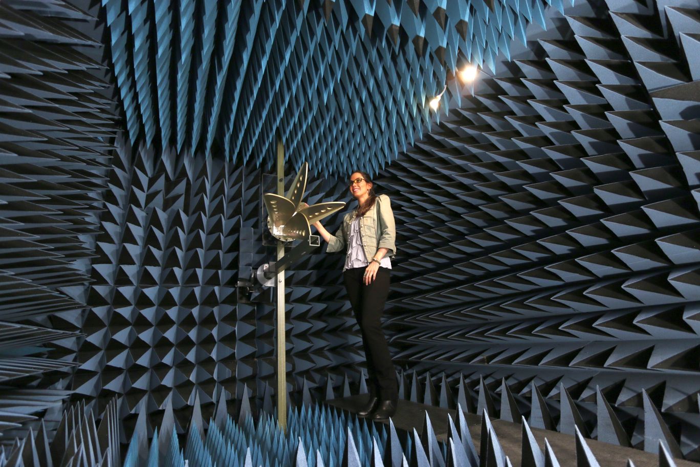
An anechoic chamber is a shielded room that has radio-wave absorbing material applied to the walls, ceiling, and floor. Chambers may be table top sized enclosures, but are normally room sized enclosures where engineers can walk in and work. The absorbers on the inside surfaces are often pyramidal shape, and give the room an unique “science fiction” look. You may have also heard that they are very expensive. So why would anyone go to all of this trouble? Because there are many benefits to antenna testing!
The Flashlight Comparison
At Antenna Test Lab Co, we often find that comparing antennas and radio waves to light is helpful in our customer’s understanding of basic concepts. We often illustrate the anechoic chamber’s functionality with the following flashlight comparison.
Imagine your task was to “pattern” a flashlight. In other words, your job is to measure and create a diagram of where the device shines light, where it does not, and how much light goes where. It may seem intuitive, because you have eyes and you can easily look at your flashlight. We are used to simply “seeing” light and it’s patterns, so it is simple to visualize a flashlight’s pattern.
However, we cannot see radio wave energy directly, so we have to measure it with radio receivers and antennas. Luckily, the propagation is very similar, so just continue to visualize light from the flashlight. Now back to your task … patterning the flashlight. Imagine that you are blind, but you have a light-meter. You can use it to measure the flashlight’s output in various directions to create the pattern of the flashlight beam. We would be using an antenna and a receiver to do the same for patterning an antenna.
You start the job and quickly discover that your light meter readings are being interfered with by the sun. Outdoors on a sunny day, your light meter is picking up lots of sunlight, and confusing that with the flashlight’s light. You need “shielding”.
Shielding
So you go indoors, to a windowless room, with the lights turned off. In this “dark room”, all of the observed light is from your flashlight under test. The room is shielded against outside light, just like the metal walls of an anechoic chamber shield our equipment from the outside radio signals. This would be the perfect solution, if it were not for one problem… reflections !
Reflections

Imagine the dark room you just chose was lined with mirrors. It is still a “dark room” and it is still fully shielded from outside light. However, the mirrored wall/ceiling/floor reflections will cause chaos with your flashlight measurements. What can be done?
You decide to paint over the mirrors with a flat black paint, one that absorbs lots of light. Now you have an optical anechoic chamber. No more reflections, or echoes. Now your test flashlight appears to be in free-space. There is no ambient light, and the walls are invisible.
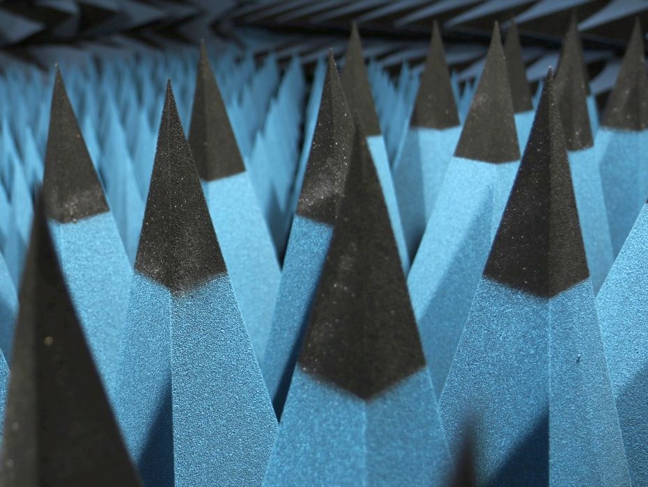
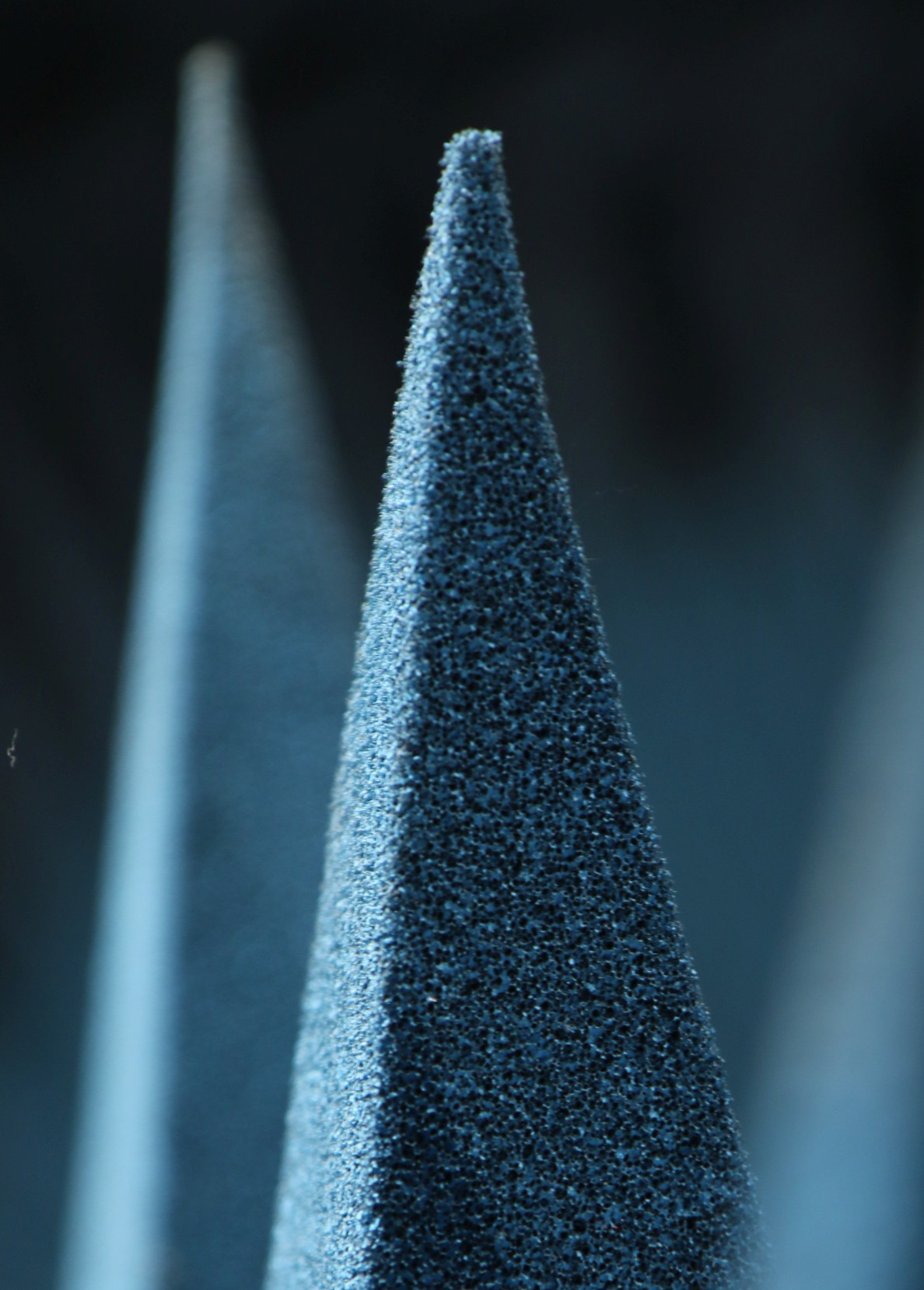
In the RF world, the reflective walls of the metallic shielded room are rendered “invisible” or “anechoic” by covering them with special RF absorbing materials. The most common absorber is the carbon loaded foam pyramid. Sharp tips on the absorbers keep RF waves from bouncing off, allowing the radio waves to slowly transition from air to the lossy carbon inside of the foam. This gradual taper from tip to core is the secret to RF absorbers. The amount of RF that bounces off of anechoic chamber walls is often 0.1% to 1% (-30 to -20 dB) of the original wave. The low level of reflections in our chamber allow us to accurately measure your antenna’s gain, efficiency, and radiation patterns. Find out more about how we do it in this educational article.
Our Anechoic Chamber
The walls, ceiling, and floor of our chamber are treated with over 2000 absorbing pyramids! The absorbers are between 12″ and 18″ long. We have an additional absorber in our chamber, 12,000 pounds of ferrite tile. The ferrite tiles absorb RF at frequencies too low for the foam pyramids, and extend the anechoic ability of our chamber down to frequencies far below many antenna testing chambers. We routinely test antennas down to 300 MHz, and product emissions down to 30 MHz.
See It For Yourself
Drop us a note, and see how we can help get your antenna project and costs on track ! Many successful companies partner with an antenna testing service, and reap the benefits.
Glossary & Terminology
- Faraday Shielding: A continuous enclosure formed by conductive material that blocks external electromagnetic fields. In chamber design, this forms the foundational metallic shell preventing ambient RF noise from entering.
- Free-Space Simulation: A theoretical RF environment with no obstacles or reflective boundaries. Anechoic chambers practically replicate free space by absorbing all stray emissions, allowing engineers to measure the pure, uninterrupted performance of an antenna.
- Pyramidal Absorber: A specialized RF-absorbing material, typically constructed from carbon-loaded polyurethane foam, shaped into geometric pyramids. The tapered physical design provides a gradual impedance transition from the air into the lossy carbon core, effectively preventing radio waves from reflecting off the boundary surface.
- Ferrite Tile: A dense, engineered magnetic ceramic material used to absorb low-frequency electromagnetic energy, typically in the 30 MHz to 1 GHz range. In hybrid chambers, they are layered beneath foam absorbers to extend the facility’s low-frequency performance.
- Acoustic Chamber: An echo-free room designed specifically to absorb sound waves rather than electromagnetic radio frequency energy. While conceptually identical to RF anechoic chambers in their goal to simulate infinite free space, acoustic chambers utilize entirely different absorbing materials, such as fiberglass wedges, to isolate audio frequencies.
Frequently Asked Questions
Why do modern anechoic chambers use both ferrite tiles and foam pyramids? Foam pyramids effectively absorb higher frequencies by matching the impedance of air and dissipating the RF energy within their carbon structures. However, at lower frequencies (typically below 1 GHz), the physical length of the foam required to absorb longer wavelengths becomes massive and structurally impractical. Ferrite tiles complement the foam by efficiently absorbing low-frequency magnetic energy while maintaining a very thin physical profile.
How do engineers verify that an anechoic chamber is actually “echo-free”? Engineers evaluate chamber performance through a calibration metric called Normalized Site Attenuation (NSA) or by conducting Voltage Standing Wave Ratio (VSWR) testing within the quiet zone. By moving a calibrated reference antenna through the designated test volume and measuring the signal at various spatial points, technicians can map the remaining multipath reflections.
Can an anechoic chamber be used to measure both transmitted patterns and receiver sensitivity? Yes. Due to the principle of antenna reciprocity, the fundamental transmit and receive properties of a passive antenna are identical. An anechoic chamber is routinely used to evaluate how efficiently a device radiates power (Total Radiated Power, TRP) as well as its operational sensitivity to detecting incoming signals (Total Isotropic Sensitivity, TIS).