- +1 919 200-0292
- info@antennatestlab.com

Return Loss and VSWR
Return Loss and VSWR
Explained Without The Math !
RF energy travels through transmissions lines (coax cables or PCB traces) just like sound travels through an empty room. It is susceptible to reflections and bounces. When sound waves hit the hard walls of an empty room, you can hear the echoes. The loss or reduction of these echoed waves is nearly zero (zero return loss). Imagine the difference when you are in a clothes packed walk-in closet… no echoes. The fabric around you absorbs sound, and the loss of the sound bounces is high (high return loss). When we send RF down a coax or PCB trace, we want it to go into the antenna (then radiate out into the world). We do not want it to bounce back towards us like sound in an empty room.
Return Loss
This bounce back reflection is called “return”. Return loss is the measure of how small the “return” or reflection/echo is. We want a small return, so a large loss on the return “echo” is good. Smaller return loss is bad, and means less energy is going into our antenna. RF engineers often measure return loss on a “dB” logarithmic scale, which can make it seem more complicated than it really is. However, just remember better return loss is indicated by bigger return loss numbers, and that is better for your antenna. Here are some examples of the logarithmic scale, or loss in decibels:
Return Loss & VSWR Table
Return Loss in dB |
What It Means |
VSWR Number |
|---|---|---|
0 dB |
100% reflection, no power into the antenna, all reflected back |
Infinite |
1 dB |
80% reflection, 20% power into the antenna |
17 |
2 dB |
63% reflection, 37% power into the antenna |
9 |
3 dB |
50% reflection, 50% power into the antenna |
6 |
5 dB |
32% reflection, 68% power into the antenna |
3.5 |
6 dB |
25% reflection, 75% power into the antenna |
3 |
8 dB |
16% reflection, 84% power into the antenna |
2.3 |
10 dB |
10 dB (10% reflection, 90% power into the antenna) |
2 |
15 dB |
15 dB (3% reflection, 97% power into the antenna) |
1.4 |
20 dB |
20 dB (1% reflection, 99% power into the antenna) |
1.2 |
As you can see, higher return losses mean more power into the antenna. Although more return loss is better here, there is little benefit above 10 dB return loss, since more that 90% of available power is already being delivered to the antenna. Return losses above 10 dB have little practical benefit.
VSWR
It officially stands for Voltage Standing Wave Ratio. This dimensionless ratio (no measurement units) is the same parameter as return loss, just expressed in a different scale. VSWR is somewhat old fashioned, and was often measured by the transmitter itself while transmitting into an antenna.
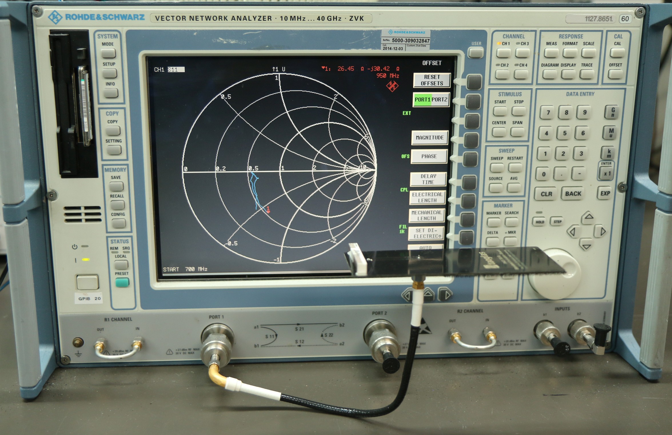
Measuring Return Loss
Measuring return loss during antenna design or verification is a powerful performance tool. Without good return loss, an antenna CANNOT accept your RF energy, and therefore cannot have it available to radiate. It is imperative that return loss goals and specifications be met. However, return loss does not tell the whole story. While it is true that poor return loss means that an antenna cannot radiate: It is NOT true that good return loss guarantees effective antenna radiation. Unfortunately, every week, we see antennas in our lab that radiate poorly, yet have a good return loss. Knowing (not assuming) your radiation efficiency is one of the many benefits of antenna testing.
Radiation Efficiency
Confusion arises because internal losses in an antenna can also create great return loss results, since the lost energy is not being reflected (returned) to the transmitter. But how do we tell if our good return loss is due to radiation (desired) or internal absorption (undesirable)? The most accurate way is to have the antenna evaluated by an antenna testing service, and verify its radiation efficiency. Good radiation efficiency is the ultimate goal for most antennas (not just good return loss).
Before investing in formal anechoic chamber testing to verify true radiation efficiency, engineers can perform rapid bench-level diagnostics to identify obvious internal losses. These techniques rely on observing how the antenna interacts with its immediate environment and analyzing its impedance bandwidth.
Tips and Tricks on Your Bench
There are two other indications of poor radiation efficiency that can be checked on a test bench:
- Step 1: The Proximity Test. While monitoring the return loss on a VNA, move your hand a few inches from the antenna. A noticeable shift in the return loss indicates that the antenna is actively “coupling” with its environment, suggesting it is actually radiating rather than burning energy internally. If your hand makes little to no difference, the antenna likely has high internal losses.
- Step 2: The Bandwidth Evaluation. Analyze the antenna’s operational bandwidth on the VNA display. An unnaturally wide bandwidth with universally “excellent” return loss is mathematically suspicious for standard resonant antennas. This often indicates the presence of severe resistive losses in the matching network or the antenna itself, effectively turning the intended antenna into a dummy load.
Your Next Steps
Are you ready for antenna insights? Partner with an antenna testing service and get results. You may contact us here.
Glossary & Terminology
- Return Loss: A measurement (usually logarithmic in dB) representing the ratio of incident power to reflected power in an RF system. Higher values indicate a better impedance match and less reflected energy. Smaller reflections (desired) are HIGHER return loss.
- VSWR (Voltage Standing Wave Ratio): A unitless measure of impedance matching that quantifies the ratio of the maximum to minimum voltage on a transmission line. Lower numbers (approaching 1.0) are better.
- Radiation Efficiency: The ratio of the total power successfully radiated by an antenna into free space to the total power accepted by the antenna from the transmission line.
- VNA (Vector Network Analyzer): An instrument used to measure the network parameters (such as return loss or S11) of electrical networks, commonly used to tune and characterize antennas on a test bench.
Frequently Asked Questions
Why is an antenna with excellent return loss still underperforming in the field? Excellent return loss only guarantees that power is successfully entering the antenna structure, not that it is radiating. High internal resistive or dielectric losses can absorb the RF energy as heat, masking a terrible radiation efficiency behind a perfect impedance match.
My antenna is receiving only, does it still need good return loss? Yes! As your antenna collects energy from the space around it, a good match is needed to transfer that RF energy to your receiver. With a poor match your antenna receives lots of RF signal, but the mismatched radio front end bounces much of the collected energy back to the antenna.
Is it worth tuning an antenna to achieve a VSWR better than 1.5? In most consumer and even commercial applications, pushing VSWR below 2.0 (roughly 10 dB return loss) or 1.5 (approx. 14 dB return loss) provides negligible real-world benefits. At 10 dB, 90% of the power is already transmitted; the engineering effort to claw back an extra 2-3% of power is rarely justified outside of highly specialized or high-power RF applications.
How does a VNA help before sending an antenna to an anechoic chamber? A VNA allows engineers to verify and tune the impedance matching network, ensuring the antenna actually accepts power at the desired operational frequencies. If the antenna is completely mismatched on the bench, chamber testing will be a waste of time and budget, as no power will radiate regardless of the antenna’s structural efficiency.