- +1 919 200-0292
- info@antennatestlab.com


Active Antennas and EIRP/TRP (in dBm)
Active Antennas and EIRP/TRP (in dBm)
Transmitter Patterns, EIRP, and TRP
Evaluating the performance of an active transmitter or “live antenna” is best accomplished through far-field Effective Isotropic Radiated Power (EIRP) measurements. By utilizing a calibrated anechoic chamber path and a precise 3D positioner, engineers can accurately map a device’s EIRP in dBm across hundreds of test directions. This comprehensive 3D pattern mapping serves as a definitive final test for any transmitter or transceiver featuring an integrated or embedded antenna. Because the results reflect the actual radiated power in the real world, this testing methodology readily exposes underlying issues with antenna performance or impedance matching networks. From this spatial data, the Total Radiated Power (TRP) of the transmitter is calculated by spherically integrating the measured EIRP values over the entire 3D pattern.
TRP Example
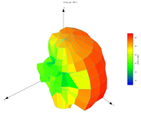
Real-world EIRP mapping often reveals significant deviations from expected antenna behavior, such as an omnidirectional device exhibiting unwanted directional gain. The shape to the left is the EIRP pattern of a 2 Watt (+33 dBm) cellular modem. Our EIRP reveals that its peak EIRP exceeds an FCC-mandated maximum of 4 Watts (+36 dBm) in a specific some orientations, despite the standard transmitter output power. Beyond verifying regulatory peak limits, integrating the spherical EIRP pattern allows engineers to determine the actual Total Radiated Power TRP. Comparing this measured TRP against the known conducted launched power entering the antenna, yields the true antenna radiation efficiency. This metric is absolutely critical for modern wireless products utilizing ultra-compact antennas, where severe physical constraints and matching network losses can sometimes reduce overall efficiency down to the 10% to 20% range.
Glossary & Terminology
- EIRP (Effective Isotropic Radiated Power): The apparent power transmitted towards the observer in a given direction, typically expressed in dBm or Watts. For an isotropic radiator, the EIRP is the same in all directions, and it also equals the TRP.
- TRP (Total Radiated Power): The absolute sum of all RF power radiated by an antenna, calculated by integrating the directional EIRP measurements over a full 3D sphere surrounding the device under test.
- Radiation Efficiency: The ratio of the total power radiated by the antenna (TRP) to the net conducted power accepted by the antenna from the connected transmitter.
- Matching Network: A circuit (usually consisting of inductors and capacitors) placed between the transmitter output and the antenna to match system impedances, minimize reflections, and maximize power transfer.
Frequently Asked Questions
Why is measured TRP typically lower than my transmitter’s conducted power? TRP accounts for all systemic losses that occur after the measurement point. This includes trace insertion loss on the PCB, losses inherent to the components in the matching network, and the physical radiation inefficiency of the antenna structure itself.
Can a device pass conducted output power limits but fail FCC EIRP limits? Yes. If the integrated antenna possesses unintended directional gain, the radiated power may concentrate in a specific direction. This concentrated EIRP beam (or bright spot) can easily exceed regulatory peak radiated limits, even if the conducted output power of the radio module remains well within compliance specifications.
How many measurement points are required for an accurate TRP calculation? For omnidirectional antennas, scanning in 15-degree increments is often sufficient. However, for electrically large devices, higher frequencies, or highly directive antenna structures, accurate TRP calculation requires a denser grid—often measurements at 5-degree or 10-degree increments across both theta and phi axes—to ensure narrow spatial nulls and peak lobes are properly captured during integration.