- +1 919 200-0292
- info@antennatestlab.com

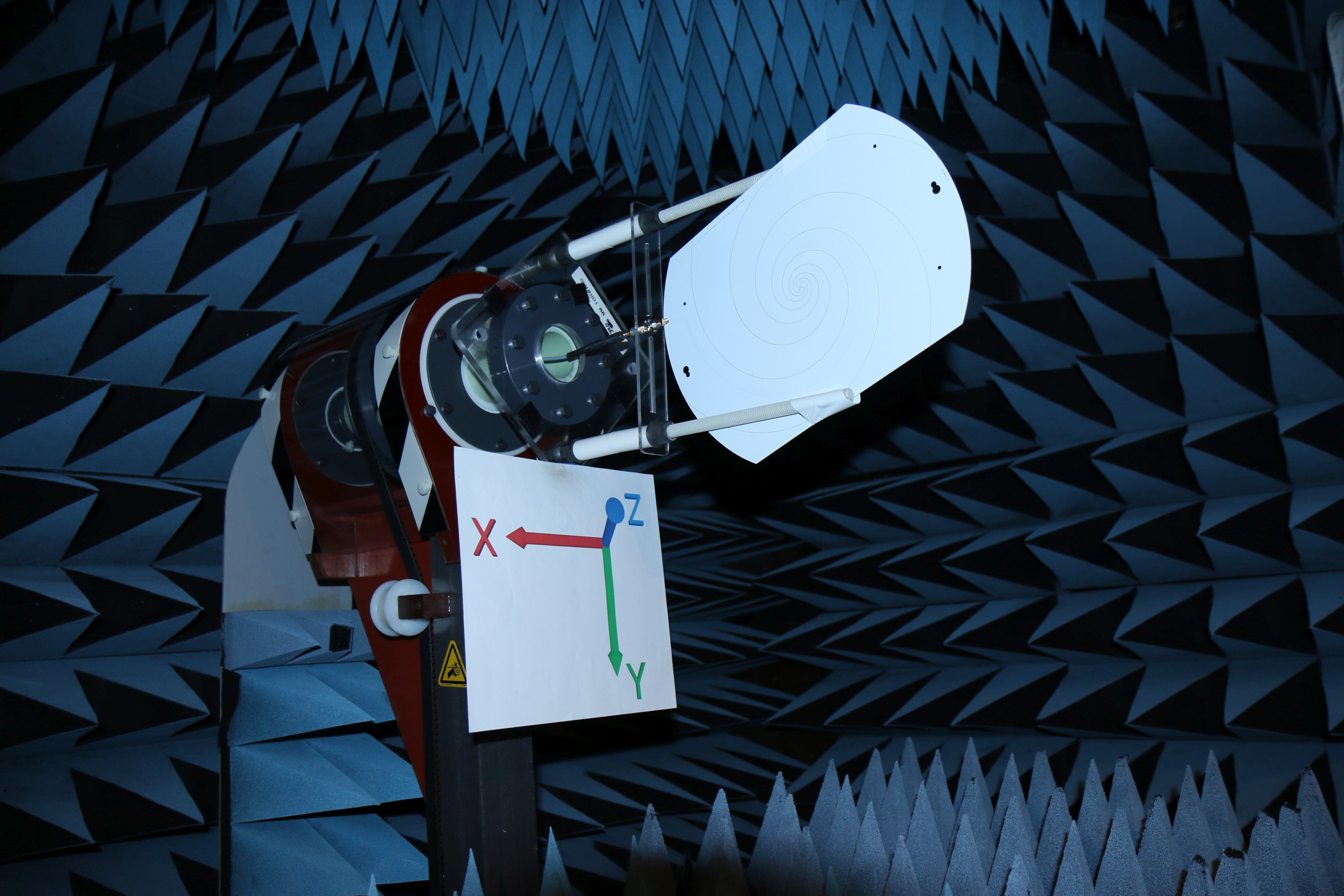
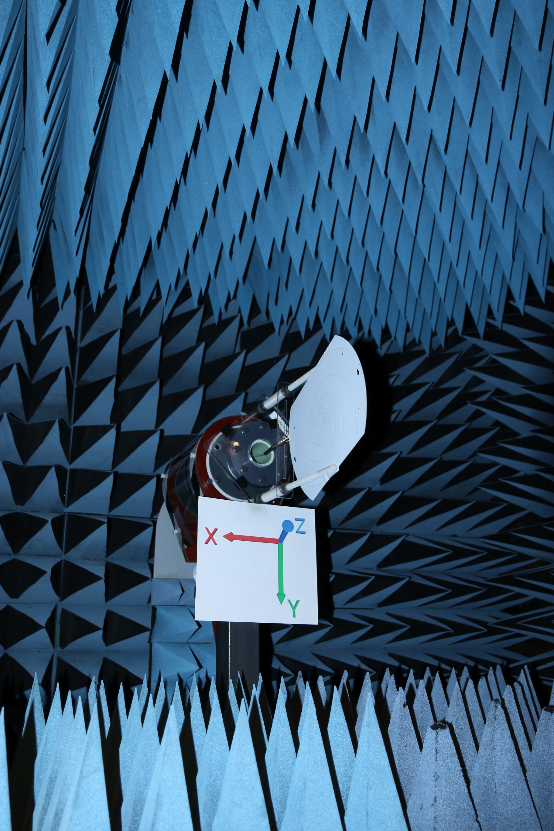
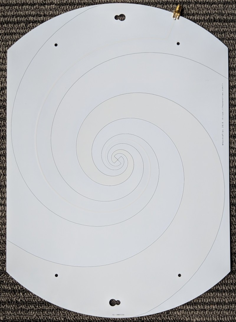
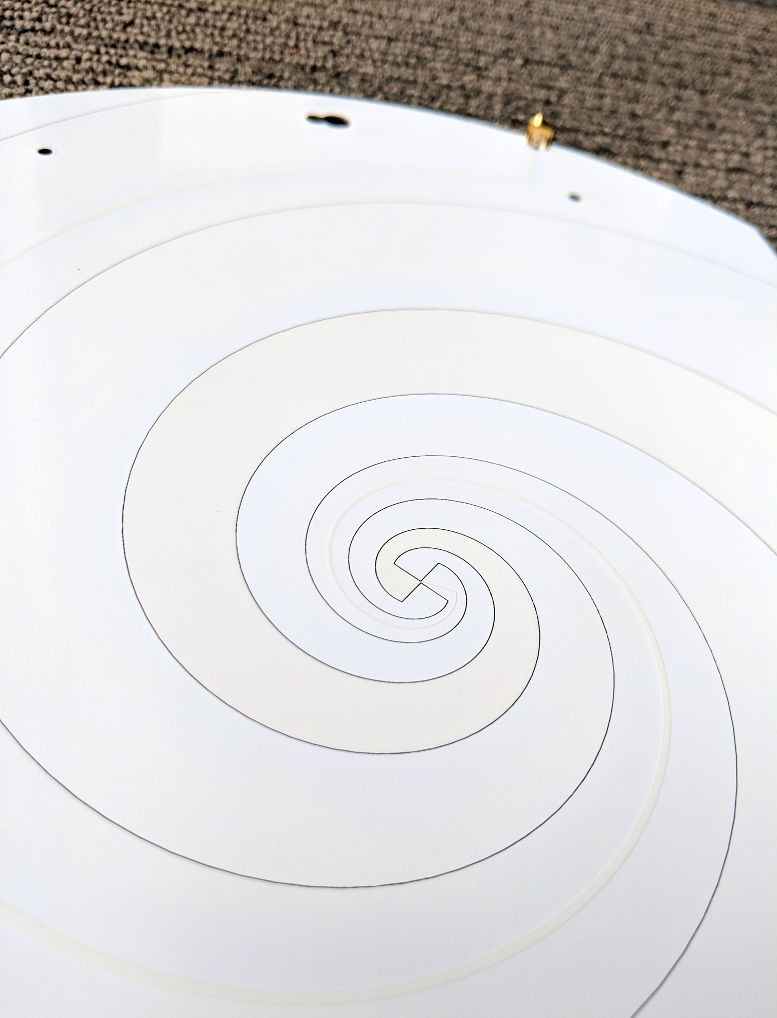
Example 11: PCB Spiral Antenna
This interesting test subject by HexandFlex is a large PCB log periodic spiral antenna (not an Archimedes spiral). Its design goal was to be circularly polarized so that it would be polarization insensitive and large enough to function down to 400 MHz. The designer’s write-up of the design flow is detailed in this series of posts, starting HERE.
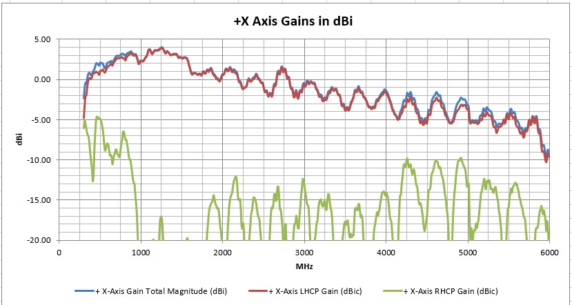
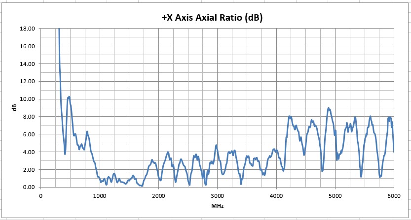
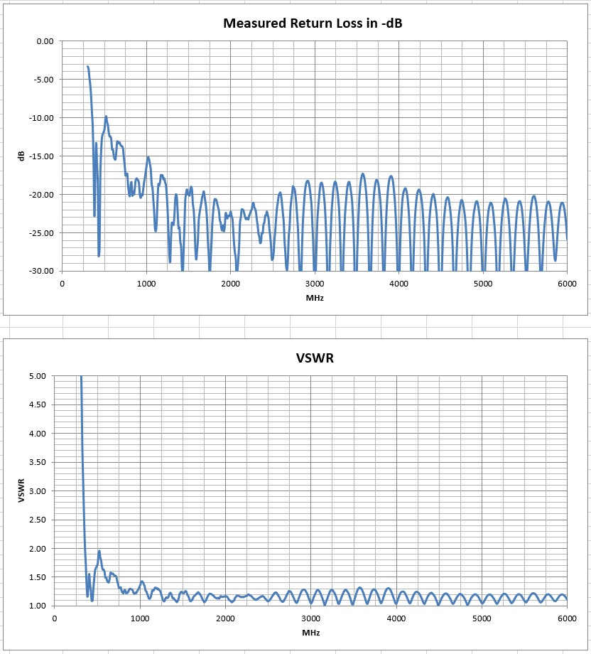
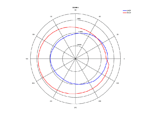
We tested this antenna from 300 MHz to 6 GHz, and found it to be very broad-banded and omni-directional (low gain) as expected. It is quite suitable for broadband reception or transmission. When the vector gain data was analyzed for the broadside direction, it had good axial ratio (good circular polarization) from about 700 MHz to 3 GHz.
It is tempting to always judge antennas on their gain graphs, but that can be misleading with omni-directional antennas. Gain vs frequency for this antenna in its broadside direction has some ripple and peaks around 1500 MHz. A better figure of merit is average gain (the spherically integrated gain from each frequency’s 3D pattern). Average gain is also the indicator of realized efficiency, and the average gain of this antenna makes it quite useful over the very broad range of 300 MHz to around 3 GHz. You can see the efficiency/average-gain graphs and data in the downloadable spreadsheets.
The Excel data set with graphs may be downloaded HERE
The 3D plot-file may be downloaded HERE
-
-
-
-

-
-
-
-
-
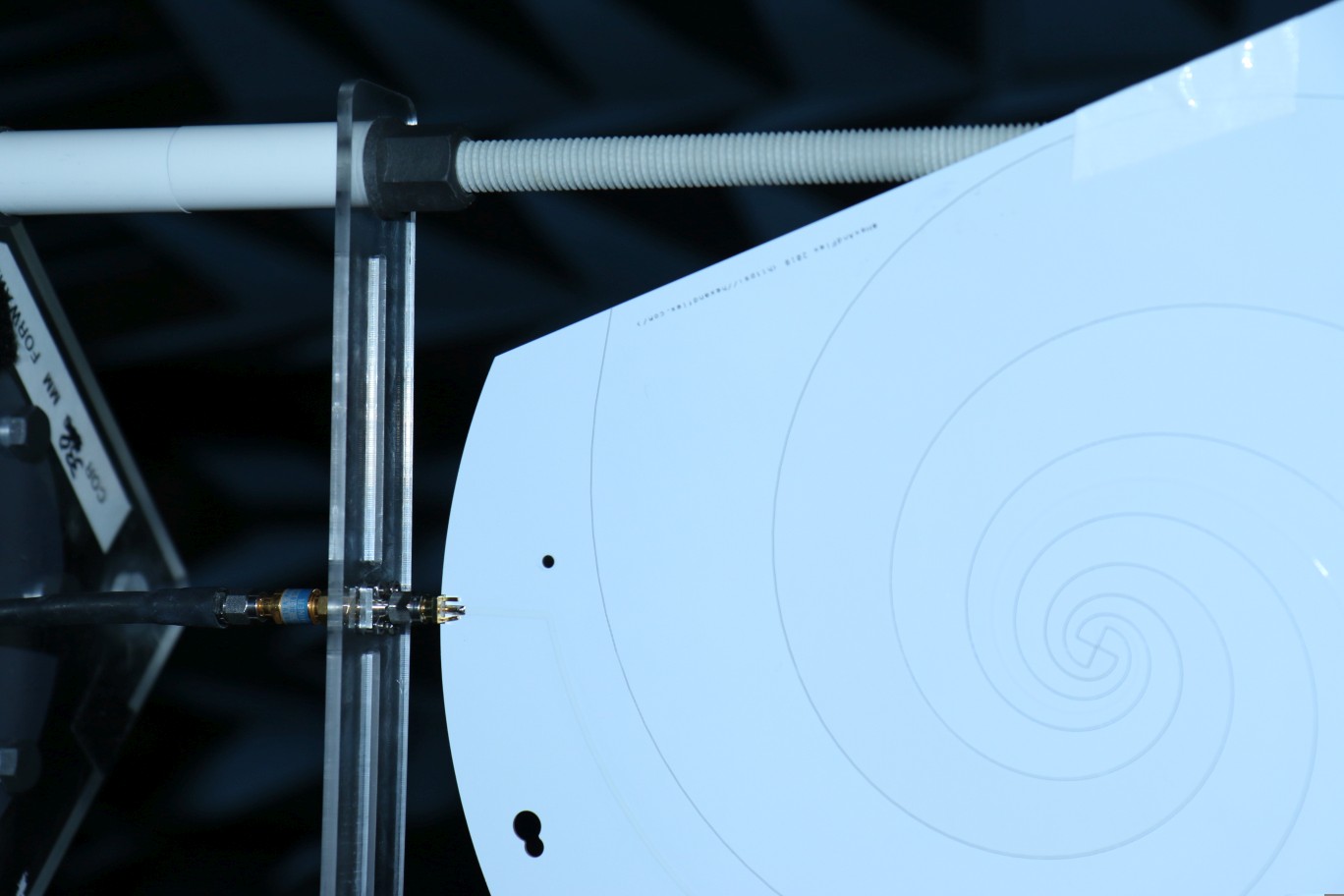
Closeup of Feed Point -
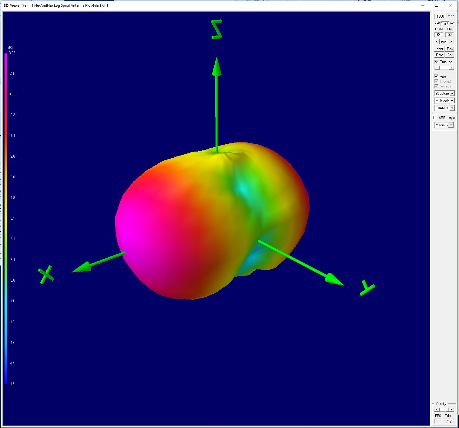
Log Spiral 3D Gain Plot at 1300 MHz

Date 05 Nov, 2018
Categories 3D Spherical Patterns, ALL Antennas, Circularly Polarized, Microwave, PCB