- +1 919 200-0292
- info@antennatestlab.com

Example 2: Polar Plots of WA5VJB Mini LPDA
Inexpensive Broadband Antenna
This sample report features a compact broadband antenna, evaluated with our 2D polar patterns at high resolution (1 degree steps). The antenna was swept from 700 MHz to 18.5 GHz in 251 steps.
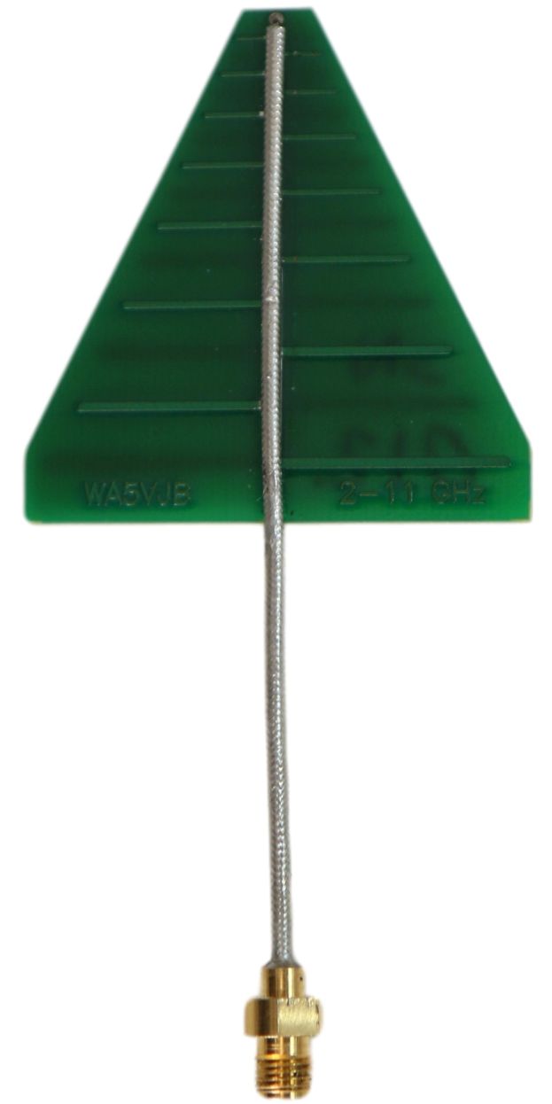
The PCB log periodic dipole array (LPDA) antenna used for this report was designed by Kent Britain WA5VJB and purchased on eBay. It is specified to operate from 2 to 12 GHz.
Background: LPDA antennas differ from Yagi antennas in that they use a compromise arrangement of shrinking elements to cover a broad range of frequencies. This design aims to minimize the number of elements and save space, while avoiding “gaps” in the operating range that can occur at frequencies between the operating lengths of the actual elements. In contrast, Yagi antennas use elements of similar size that operate together in a narrow band of frequencies.
Results: The measured forward gain was typically between 2 and 6 dBi over the specified operating range. The report includes graphs of gain vs frequency, as well as our interactive variable frequency polar plots. As always, all data is provided in Excel spreadsheet format, allowing for additional plots and post-analysis. The results spreadsheet can be downloaded HERE.