- +1 919 200-0292
- info@antennatestlab.com

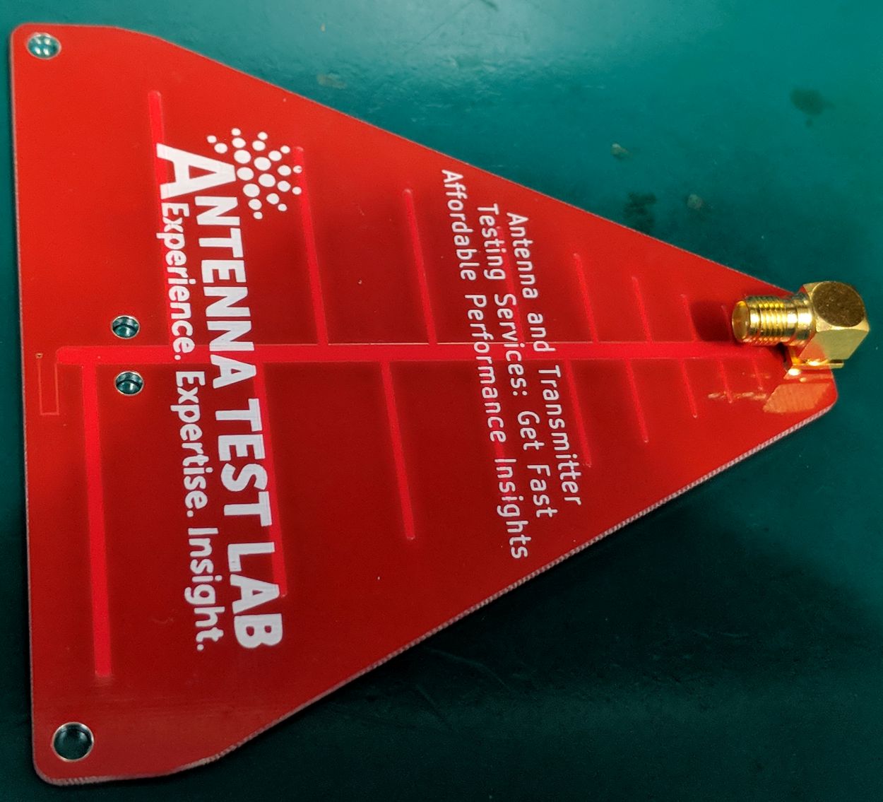
PCB0042 LPDA Tile Antenna
PCB0042 LPDA Tile Antenna
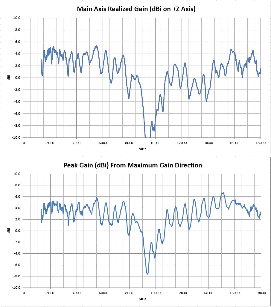
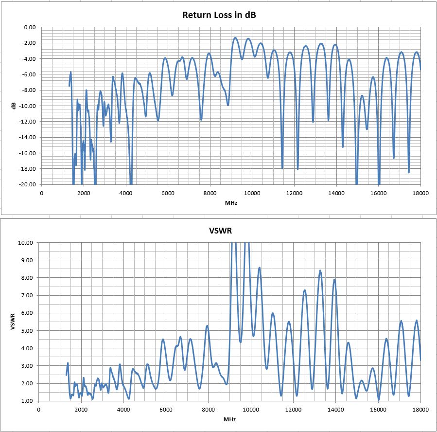
This 10 cm “tile” sized antenna works well from about 1300 MHz to 8 GHz with 4 dBi of gain and good return loss.
It is fed by a standard “5-pin” PCB mounted right-angle SMA jack. Just trim two off ground pins as shown in the photo below before soldering. This creates a simple SMA feed connection. Log Periodic Dipole Array antennas have a range of resonant elements that work over a broad frequency range. LPDAs are fed from the “front” of the antenna, and its directivity is from the “small elements end” of the antenna. The feed-line exits from the rear of the antenna as shown by the direction of the right angle SMA connector.
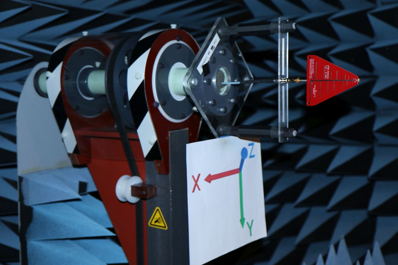
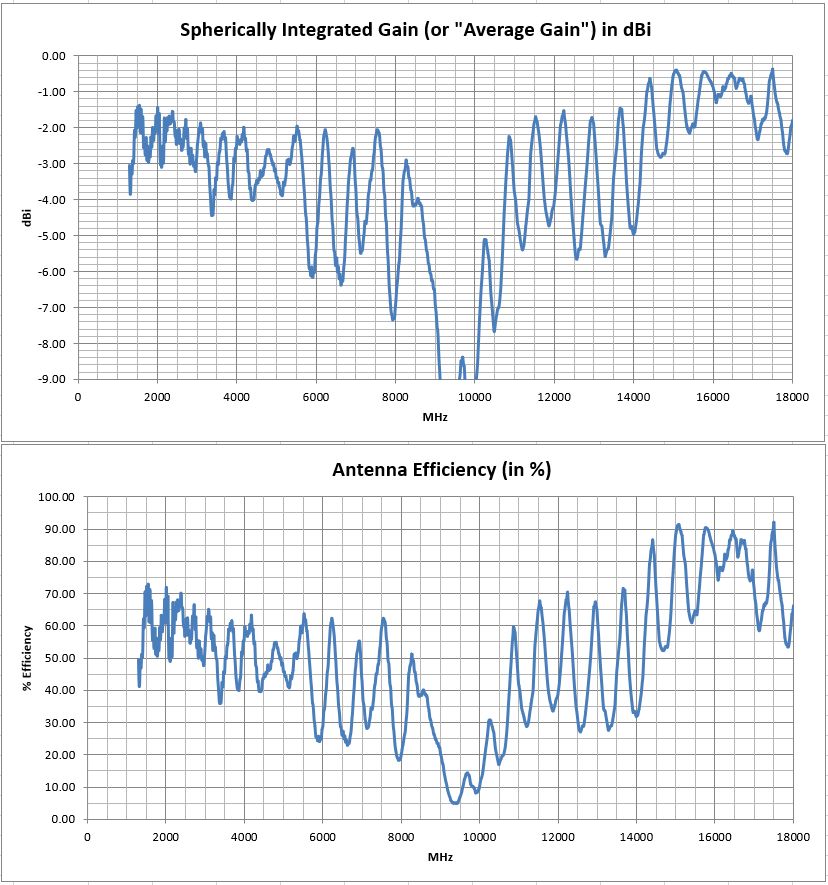
A full Excel spreadsheet 3D gain results report can be downloaded HERE. This extensive test program covers full 3D spherical gain patterns (standard resolution of 10 degrees) at 1671 stepped frequencies from 1300 MHz to 18 GHz in 10 MHz steps. The test report details higher level performance data, such as: Forward Gain, Peak Gain, Radiation Efficiency, and VSWR/Return-Loss vs Frequency.
We can test your antenna project too! We have a full range of testing services listed HERE

We hope you enjoy your sample antenna. We do not offer antenna design services here so that we may focus customer design confidentiality. These “biz card” antennas are just for fun, and they are not for sale. Inspiration for this PCB design came from Kent Britain WA5VJB, who does sell PCB antennas. His website is HERE.