- +1 919 200-0292
- info@antennatestlab.com

PCB0045 Vivaldi Broadband Antenna
Search results for:
PCB0045 Vivaldi Broadband Antenna
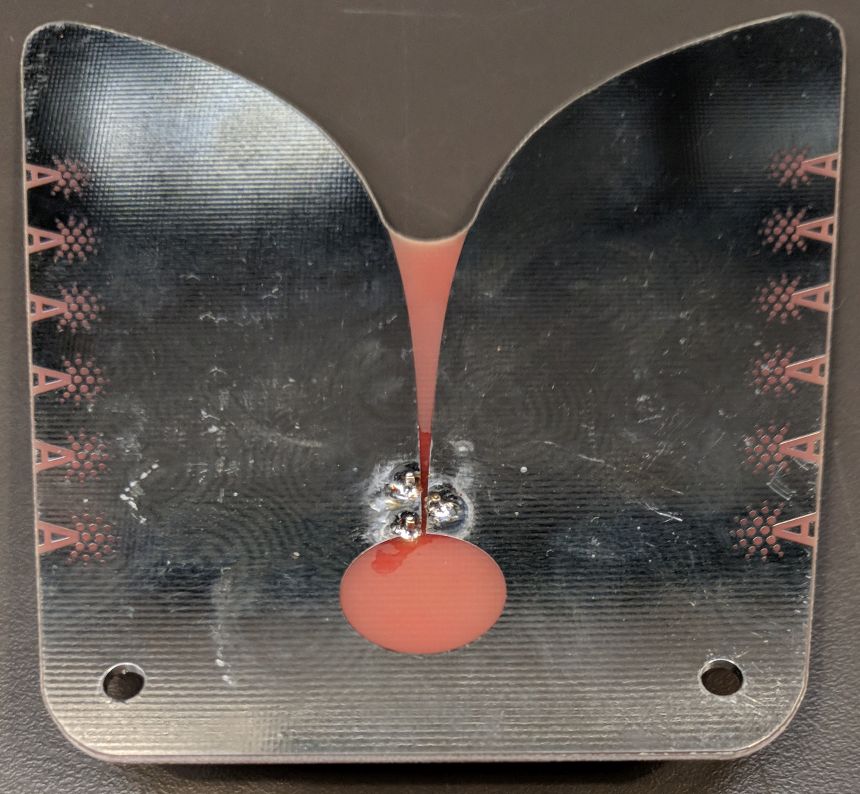
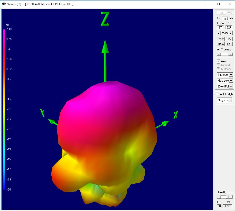
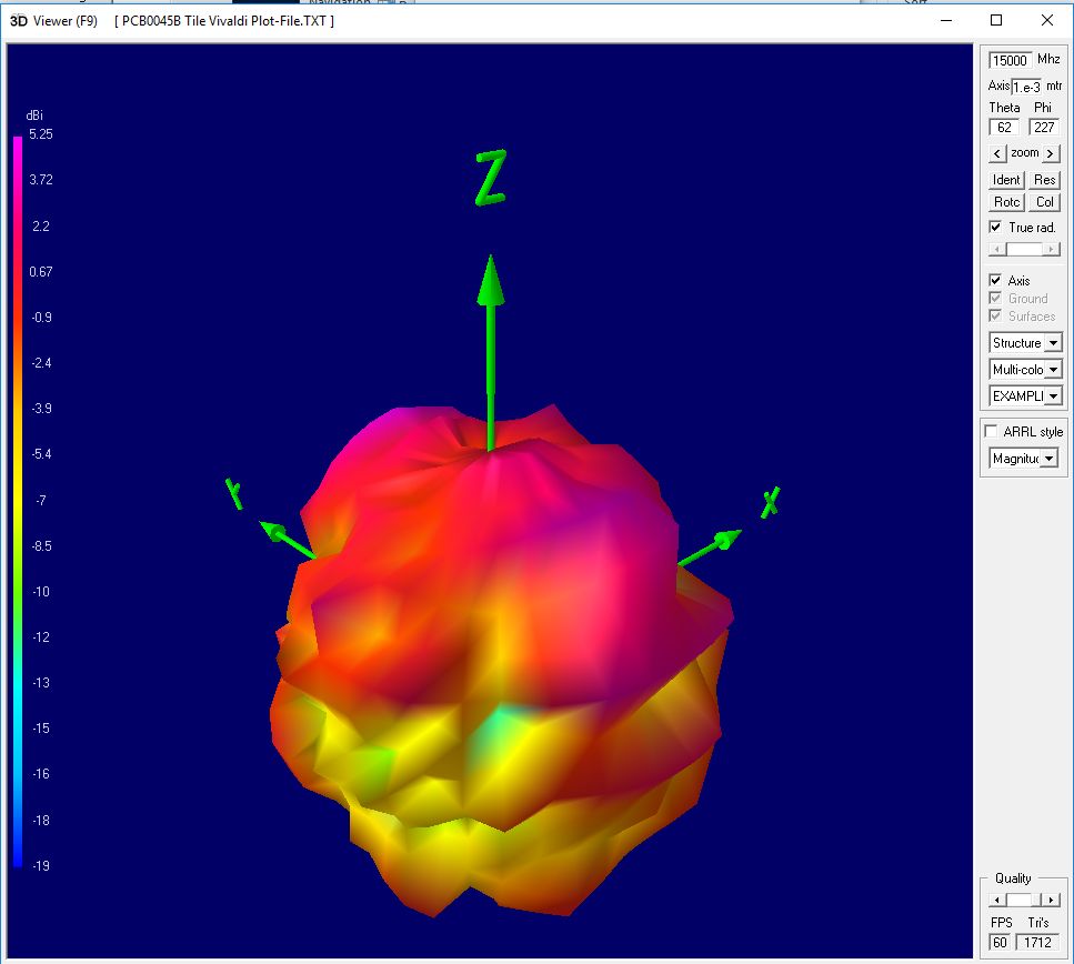
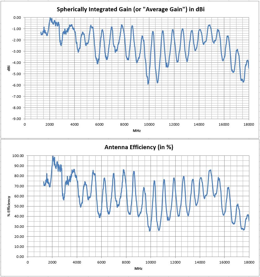
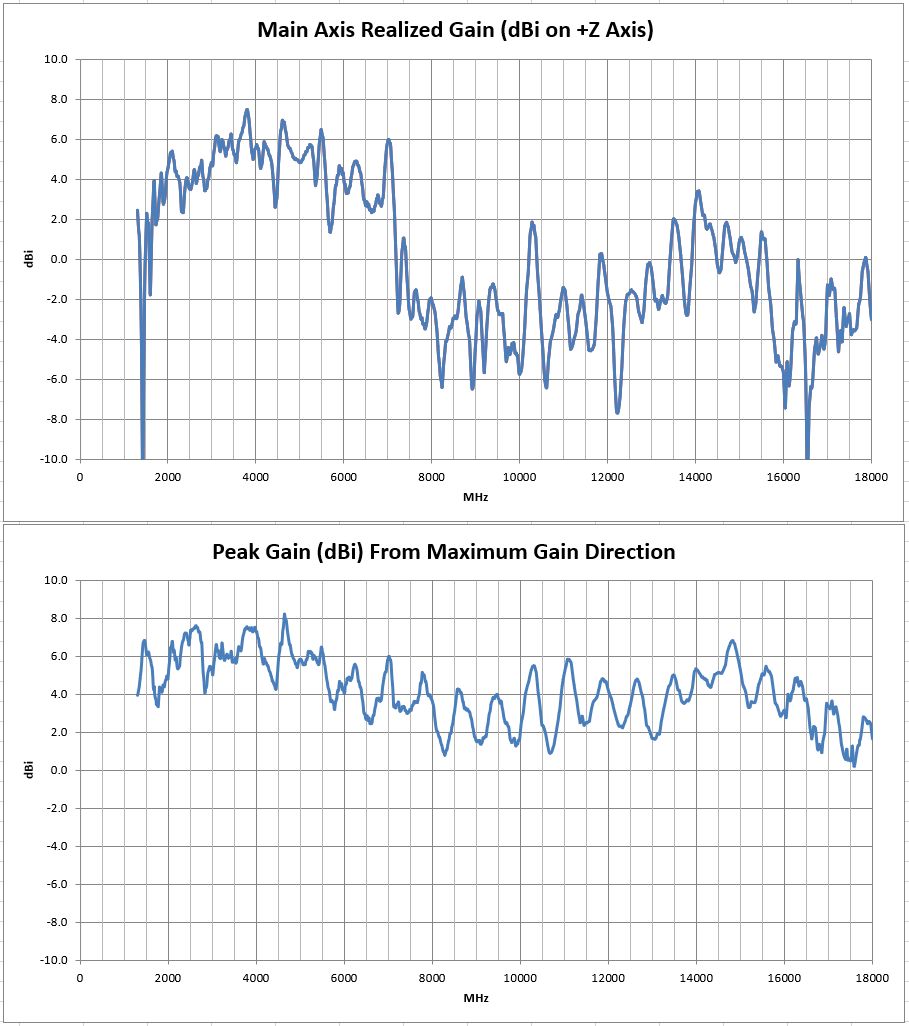
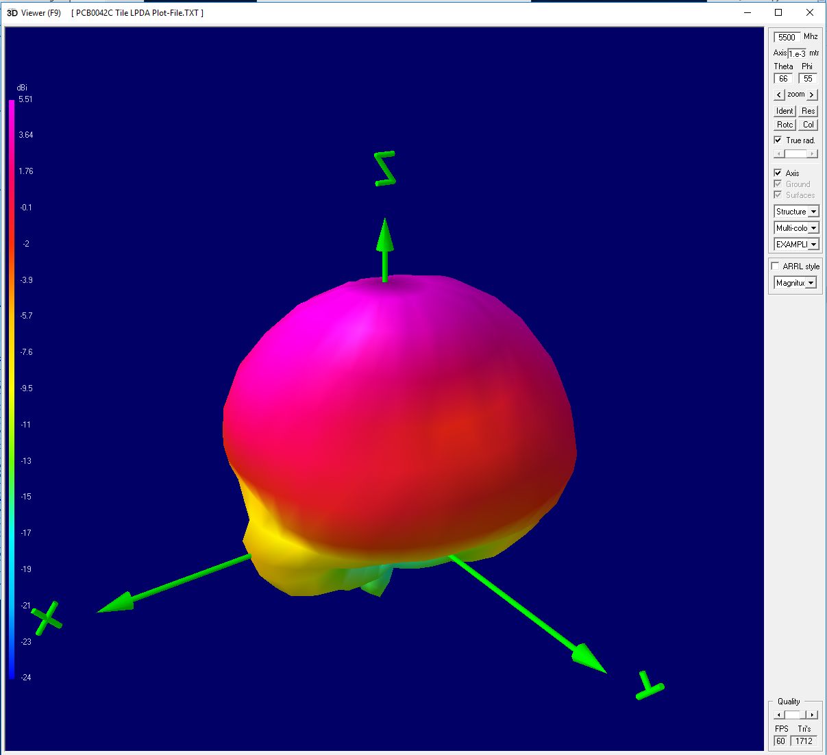
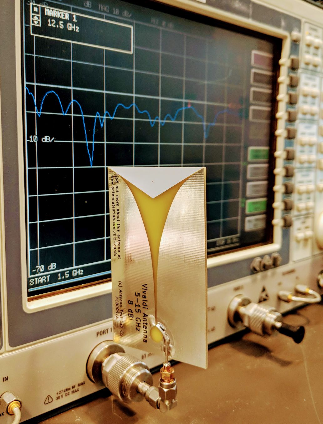
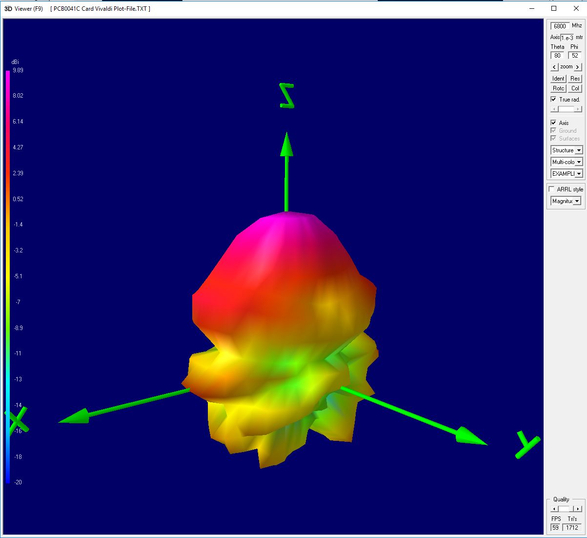
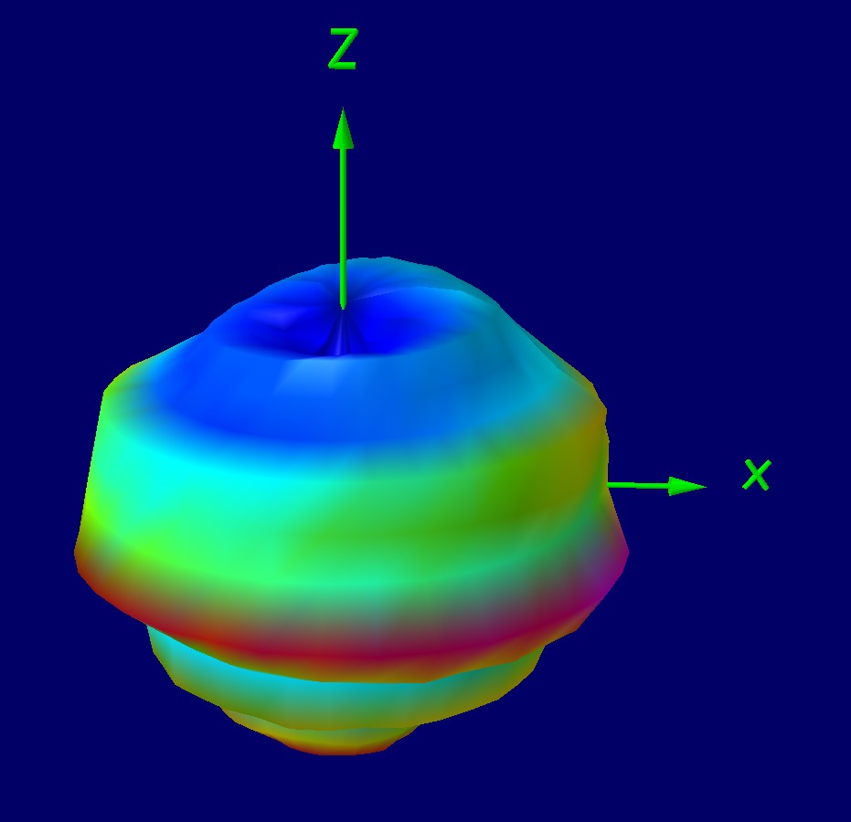
This functional 10cm “tile” sized Vivaldi antenna works well from about 1500 MHz to 7 GHz. It has forward gain averaging 4 to 6 dBi along its main axis. From 7 to 18 GHz it also displays forward gain, although the main “beam” breaks up and peak gain is not right along the +Z axis. This effect can be seen by comparing the 3D gain plots at 3800 MHz and 15 GHz below. Please note, full 3D plots are available at all 1671 test frequencies! A 1300 MHz to 18 GHz forward (and peak) gain graph is also shown below.
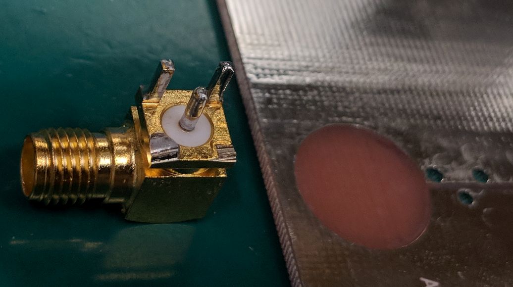
This antenna is fed by a standard “5-pin” PCB mounted right-angle SMA jack, oriented away from the back of the antenna as shown.
A full Excel spreadsheet 3D gain results report can be downloaded HERE. This extensive test program covers full 3D spherical gain patterns at 1671 stepped frequencies from 1300 MHz to 18 GHz in 10 MHz steps. The test report details higher level performance data, such as: Forward Gain, Peak Gain, Radiation Efficiency, and VSWR/Return-Loss vs Frequency.
The full set of 1671 spherical plot-files can be downloaded HERE in “zipped” format. Unzip and use this plot-file along with our downloadable 3D plotting software HERE. Then create rotate-able/scale-able 3D plots on your own desktop at any test frequency.
Please remember – We can test your antenna project too! We have a full range of testing services listed HERE


We hope you enjoy your sample antenna. We do not offer antenna design services here so that we may focus customer design confidentiality. These “biz card” antennas are just for fun, and they are not for sale.
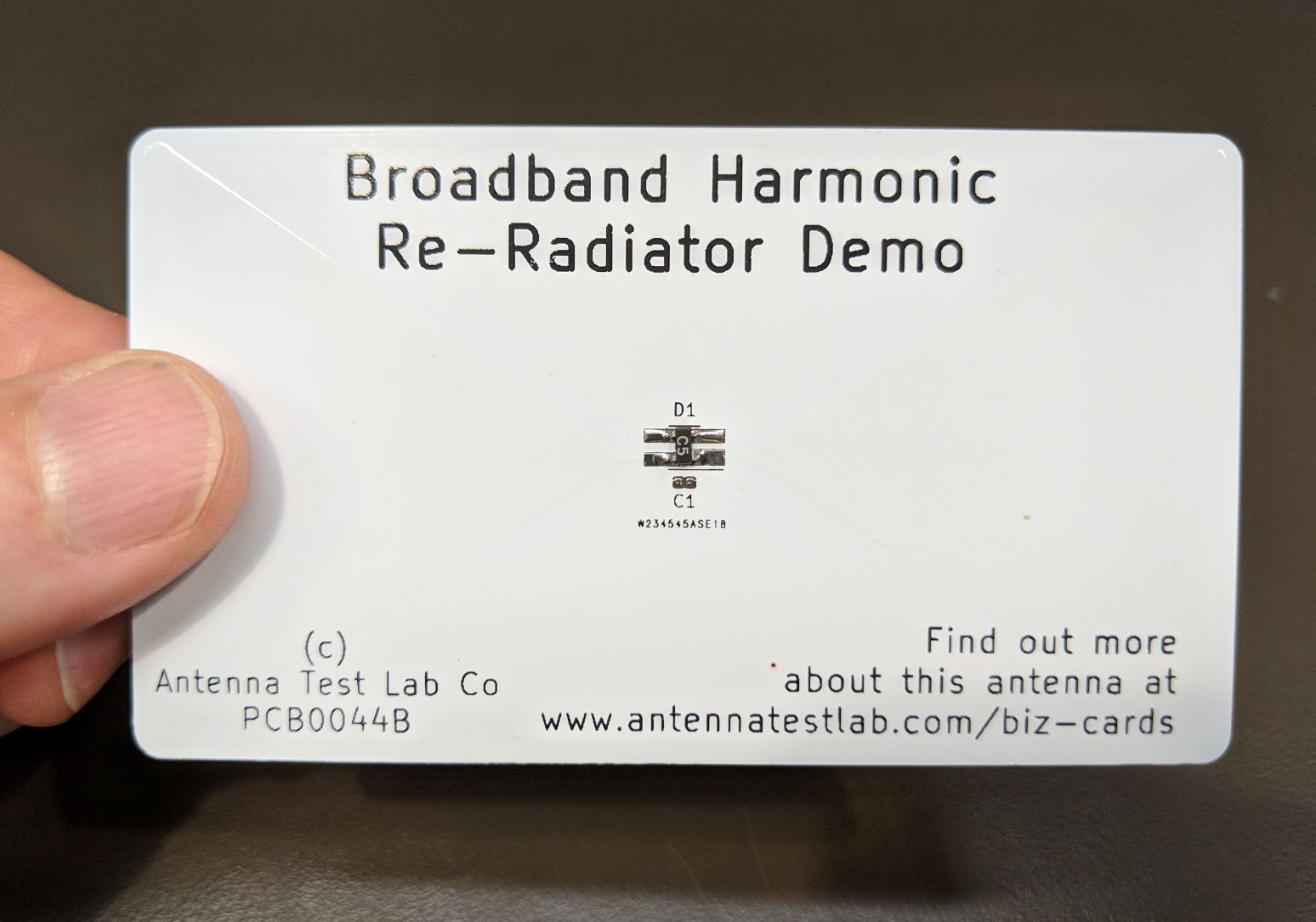
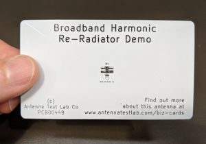
PCB0044 PIM Harmonic Re-Radiator
This small circuit board was our original business card. It was born out of the repeated experience of trying to convince cellular clients that their transmitter’s radiated spurious harmonics were probably re-radiated. Often, RF engineers assume harmonic spurs come directly from their transmitter and radiate from the device’s antenna.
While this can be true in many cases, it is not always the culprit. In “higher power” transmitters (say 1 Watt and above), semiconductor parts located near an embedded antenna can rectify their near field induced RF currents and produce additional “products”, like intermodulation or radiated spurious harmonics.
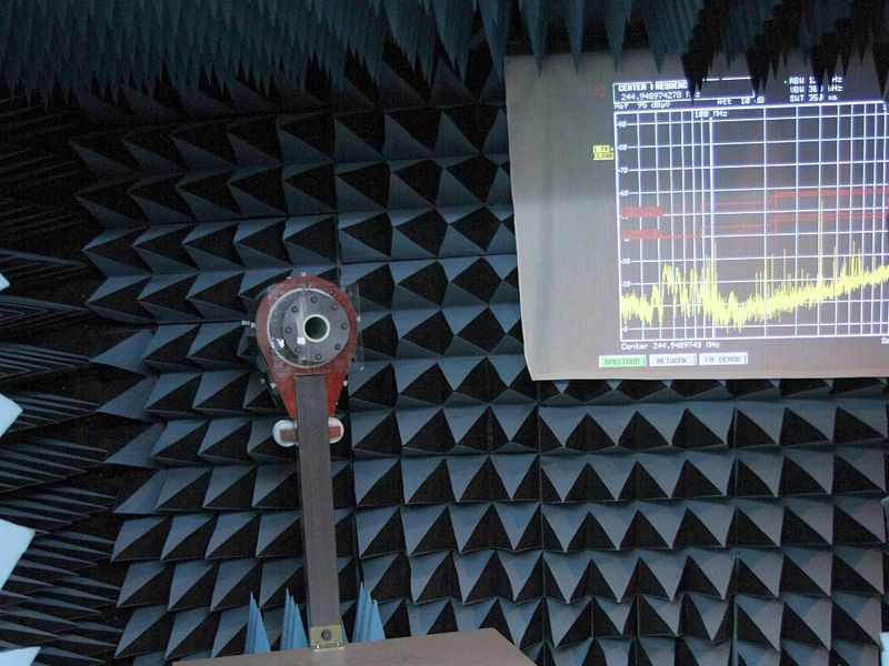
In the Antenna Test Lab anechoic chamber, there is a 5 foot projection screen used to display real time spectrum analyzer results. The demonstration would be as follows. While looking at the first or second harmonic level in real time on the big screen, this “business card” can be moved into proximity of the live transmitter and raise the radiated harmonics to well above legal limits. It was always living proof to those who doubted re-radiation products, and helps us focus on resolving radiated spurious emissions problems.
The biz-card PCB is a broadband shaped biconical antenna with a diode at the center. Induced RF current is rectified to create non-linear products, which in turn re-radiate and are picked up in the far field as compliance failures. The card is passive and does not have a battery or transmitter. Yet its proximity to a transmitter can cause excessive spurious emissions. There is also a pad location on the card for an 0402 capacitor. Simply placing 10 pF in this location effectively “shorts out” or decouples the RF diode and “fixes” the problem. The same is done on the customer’s circuitry, now that they understand the problem !
Please remember – We can test your transmitter project too! We have a full range of testing services listed HERE
We hope you enjoy your sample antenna. We do not offer antenna design services here so that we may focus customer design confidentiality. These “biz card” antennas are just for fun, and they are not for sale.
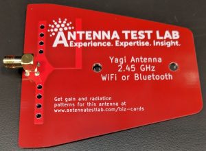
PCB0043 WiFi or Bluetooth Yagi Antenna
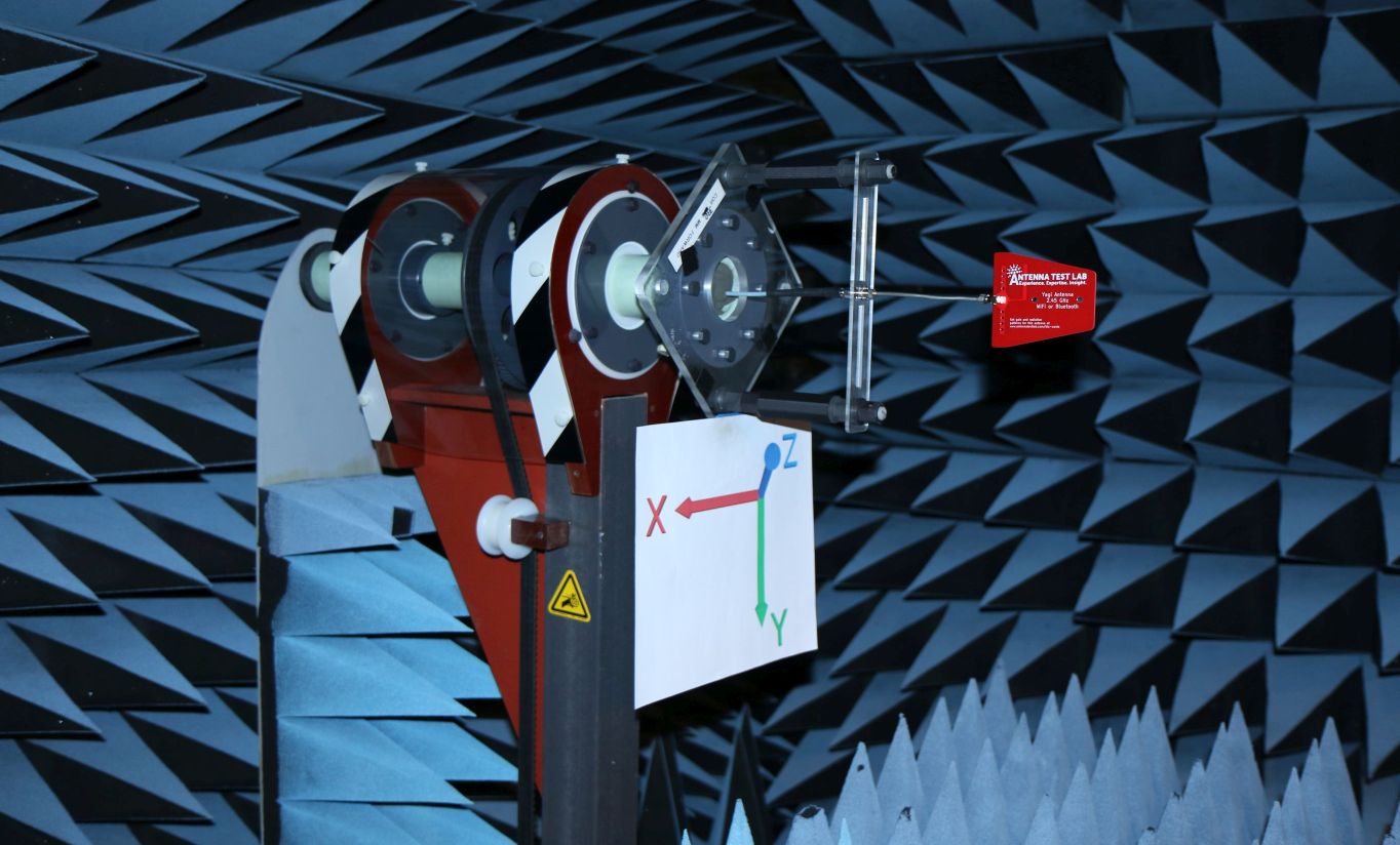
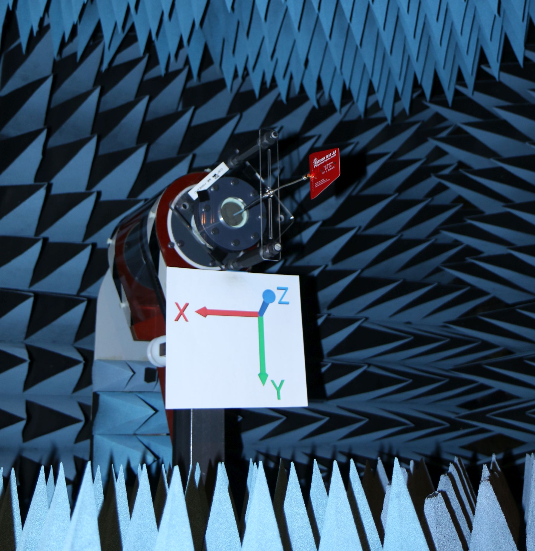
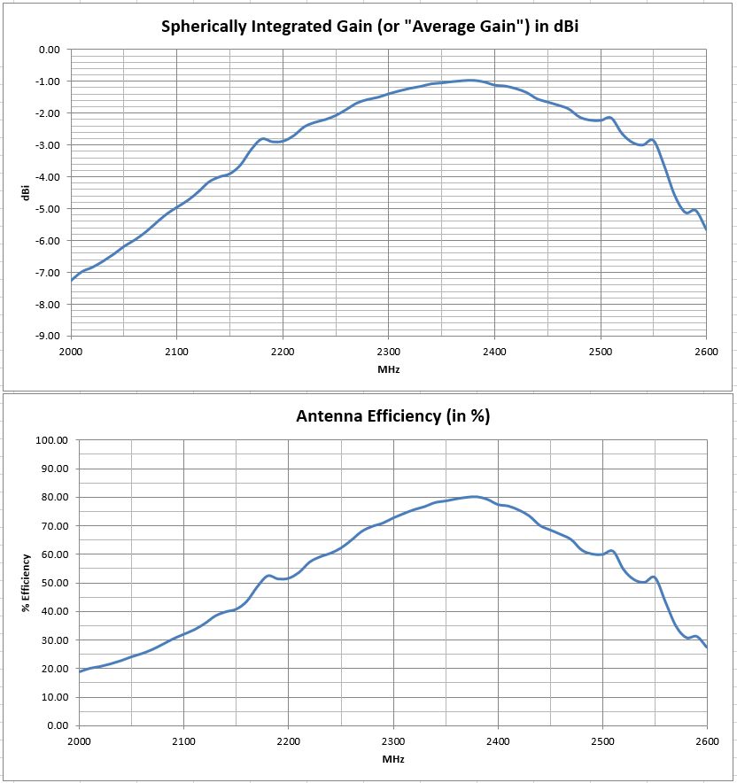
This 10 cm “tile” sized antenna works well in its design range for the 2.45 GHz ISM band. Use it for WiFi, Bluetooth, or any other service that uses this universally popular unlicensed radio band.
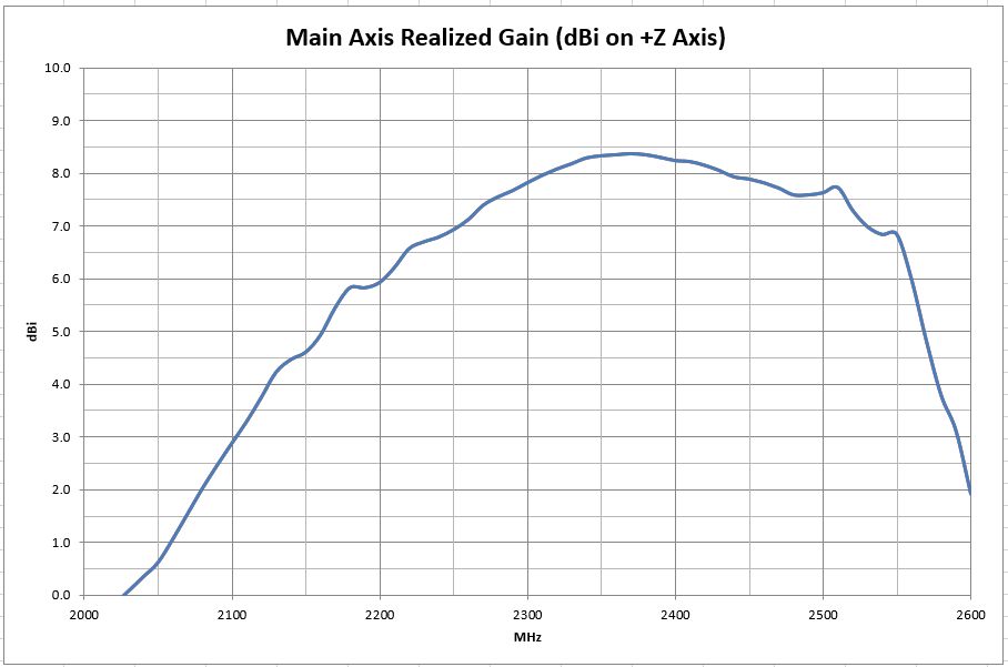
Performance is great for an inexpensive antenna built on low price FR4 PCB material. It has a forward gain of 8 dBi, a directivity of 9 dB, and an radiation efficiency of -1 dB (80%). Those three numbers help illustrate the interrelationship of gain and directivity, which are related by efficiency. If the antenna were lossless (perhaps a better PCB material or all-metal construction) then the directivity would still be 9 dB., but gain would also be 9 dBi.
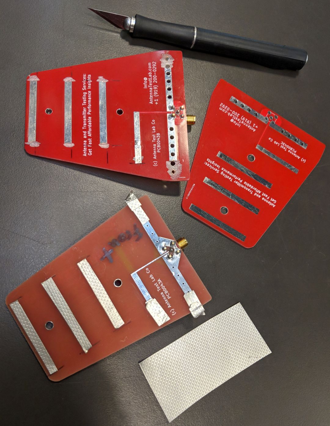
It is fed by a standard “5-pin” PCB mounted right-angle SMA jack, oriented away from the back of the antenna as shown.
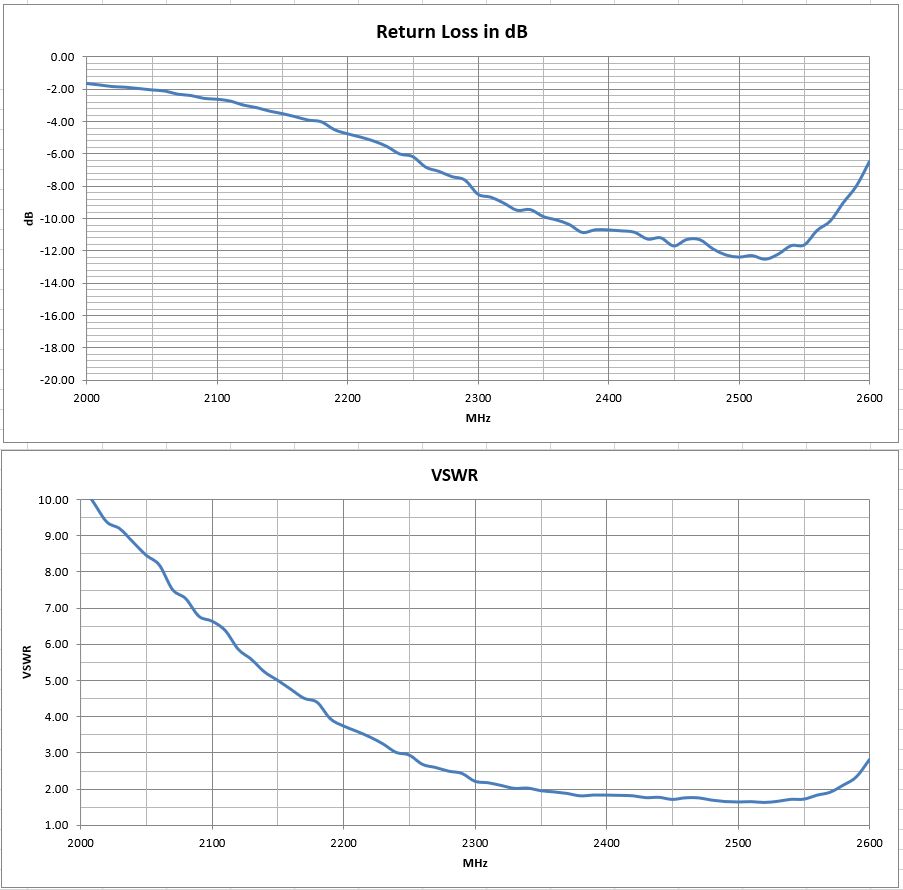
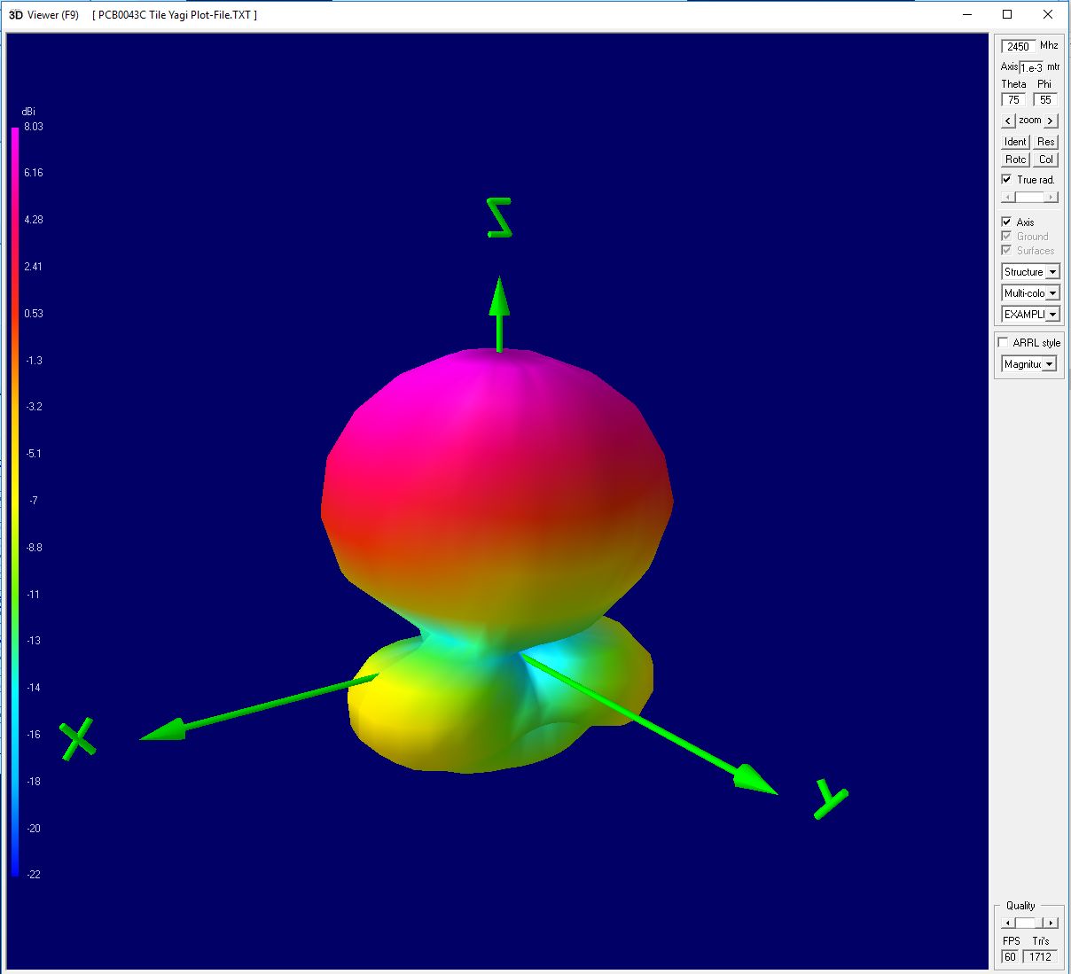
A full Excel spreadsheet 3D gain results report can be downloaded HERE. This test program covers full 3D spherical gain patterns at 61 stepped frequencies from 2000 MHz to 2600 MHz in 10 MHz steps. The test report details higher level performance data, such as: Forward Gain, Peak Gain, Radiation Efficiency, and VSWR/Return-Loss vs Frequency.
The full set of 61 spherical plot-files can be downloaded HERE in “zipped” format. Unzip and use this plot-file along with our downloadable 3D plotting software HERE. Then create rotate-able/scale-able 3D plots on your own desktop at any test frequency.
Please remember – We can test your antenna project too! We have a full range of testing services listed HERE
We hope you enjoy your sample antenna. We do not offer antenna design services here so that we may focus customer design confidentiality. These “biz card” antennas are just for fun, and they are not for sale.
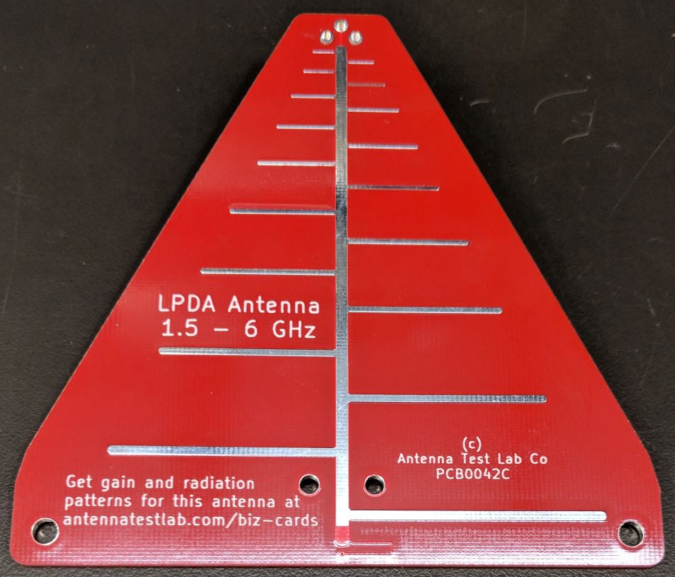
PCB0042 LPDA Tile Antenna
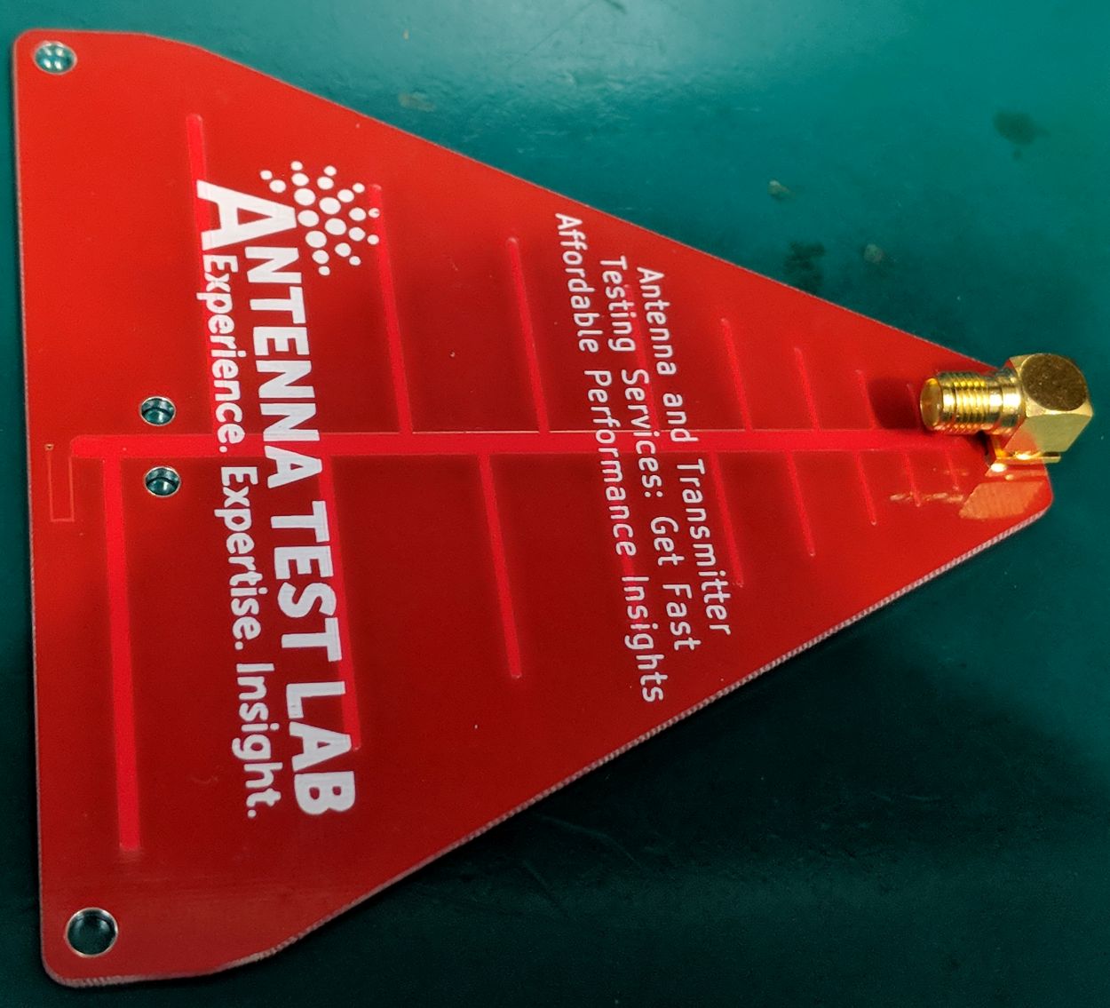
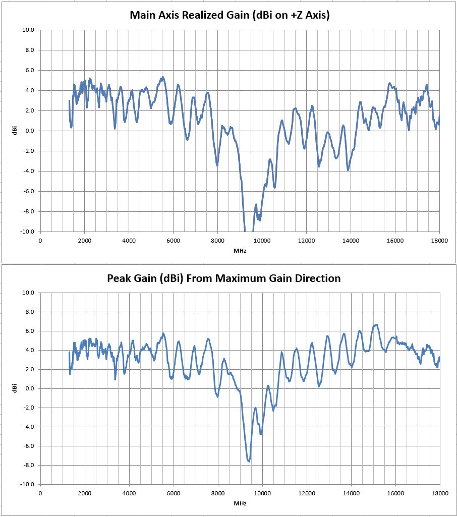
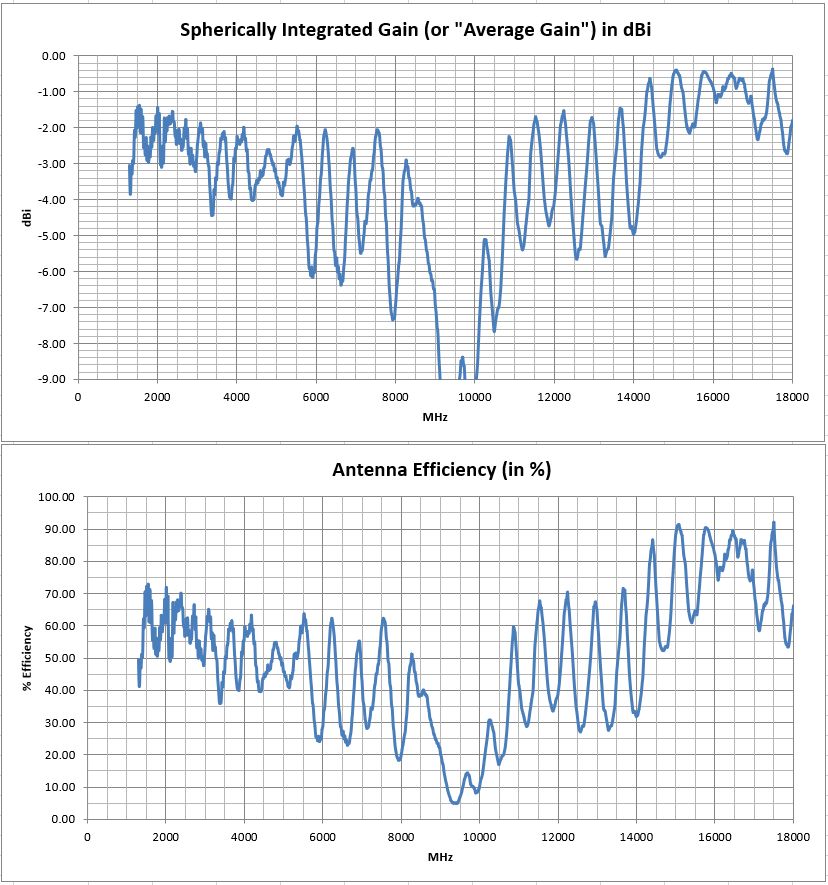
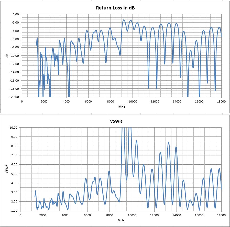
This 10 cm “tile” sized antenna works well from about 1300 MHz to 8 GHz with 4 dBi of gain and good return loss.
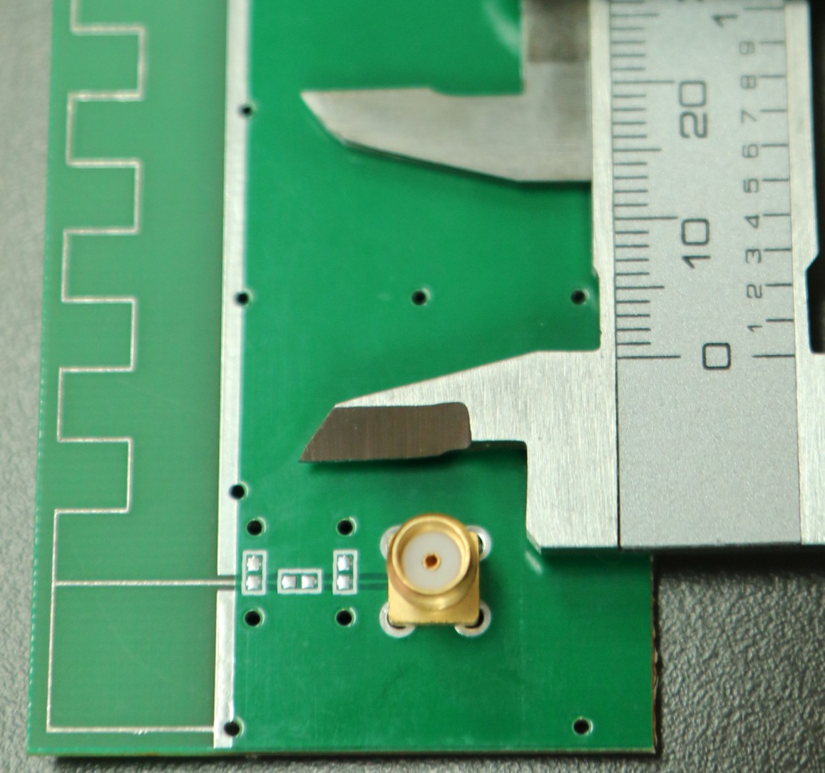
It is fed by a standard “5-pin” PCB mounted right-angle SMA jack. Just trim two off ground pins as shown in the photo below before soldering. This creates a simple SMA feed connection. Log Periodic Dipole Array antennas have a range of resonant elements that work over a broad frequency range. LPDAs are fed from the “front” of the antenna, and its directivity is from the “small elements end” of the antenna. The feed-line exits from the rear of the antenna as shown by the direction of the right angle SMA connector.
A full Excel spreadsheet 3D gain results report can be downloaded HERE. This extensive test program covers full 3D spherical gain patterns at 1671 stepped frequencies from 1300 MHz to 18 GHz in 10 MHz steps. The test report details higher level performance data, such as: Forward Gain, Peak Gain, Radiation Efficiency, and VSWR/Return-Loss vs Frequency.
The full set of 1671 spherical plot-files can be downloaded HERE in “zipped” format. Unzip and use this plot-file along with our downloadable 3D plotting software HERE. Then create rotate-able/scale-able 3D plots on your own desktop at any test frequency.
Please remember – We can test your antenna project too! We have a full range of testing services listed HERE

We hope you enjoy your sample antenna. We do not offer antenna design services here so that we may focus customer design confidentiality. These “biz card” antennas are just for fun, and they are not for sale. Inspiration for this PCB design came from Kent Britain WA5VJB, who does sell PCB antennas. His website is HERE.
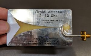
PCB0041 Vivaldi Business Card Antenna
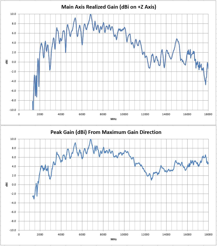
This functional business card sized antenna works well from about 2 to 10 GHz. It has forward gain averaging 4 to 6 dBi and a peak gain of 10 dBi at 6.75 GHz. A full 1300 MHz to 18 GHz forward (and peak) gain graph is shown below.
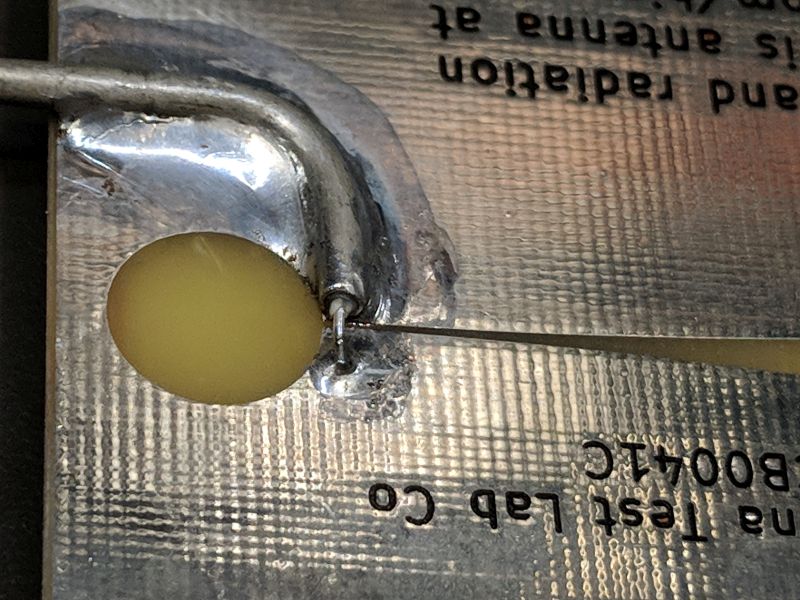
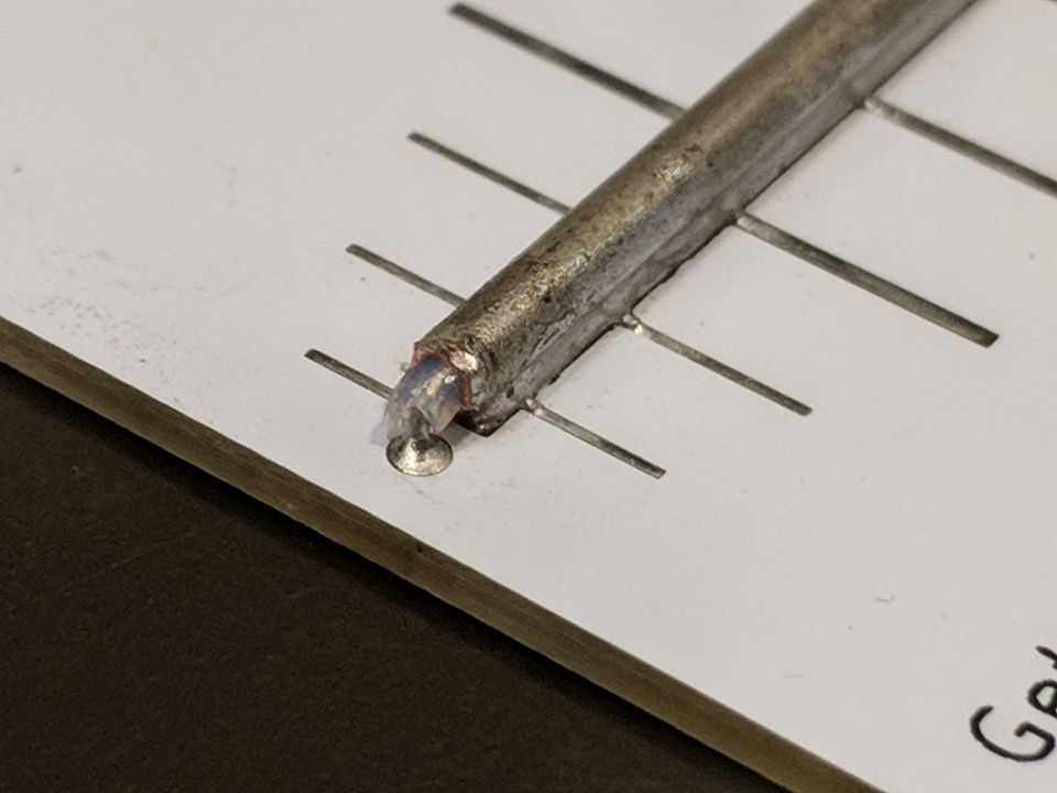
It is fed by a soldered down section of semi-rigid coax as shown in the photographs below. For convenience, just use a scrap of coax that is already terminated with an SMA. Connect the center and shield of the coax to opposite sides of the tapered slot, keeping your dimensions as small as possible. The feed-line exits from the rear of the antenna as shown.
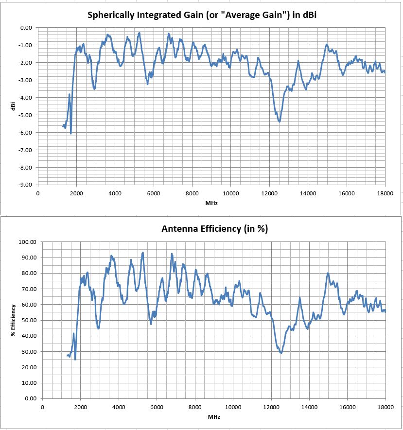
A full Excel spreadsheet 3D gain results report can be downloaded HERE. This extensive test program covers full 3D spherical gain patterns at 1671 stepped frequencies from 1300 MHz to 18 GHz in 10 MHz steps. The test report details higher level performance data, such as: Forward Gain, Peak Gain, Radiation Efficiency, and VSWR/Return-Loss vs Frequency.
The full set of 1671 spherical plot-files can be downloaded HERE in “zipped” format. Unzip and use this plot-file along with our downloadable 3D plotting software HERE. Then create rotate-able/scale-able 3D plots on your own desktop at any test frequency.
Please remember – We can test your antenna project too! We have a full range of testing services listed HERE


We hope you enjoy your sample antenna. We do not offer antenna design services here so that we may focus customer design confidentiality. These “biz card” antennas are just for fun, and they are not for sale.
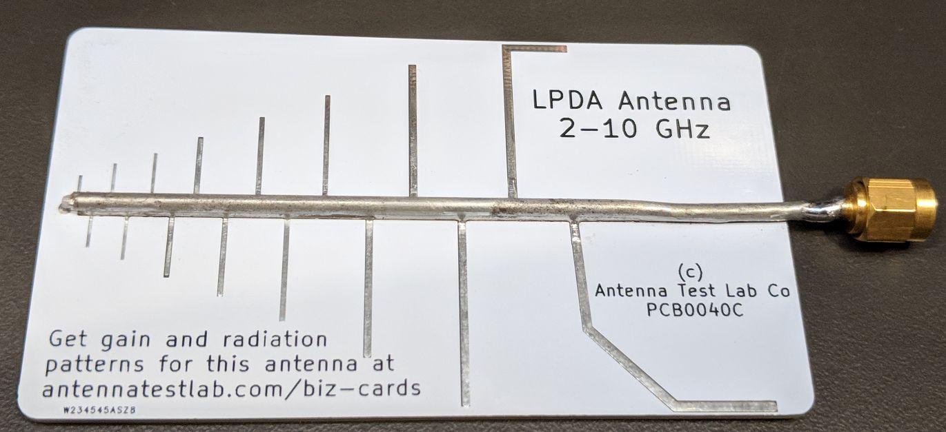
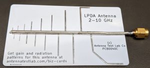
PCB0040 LPDA Business Card Antenna
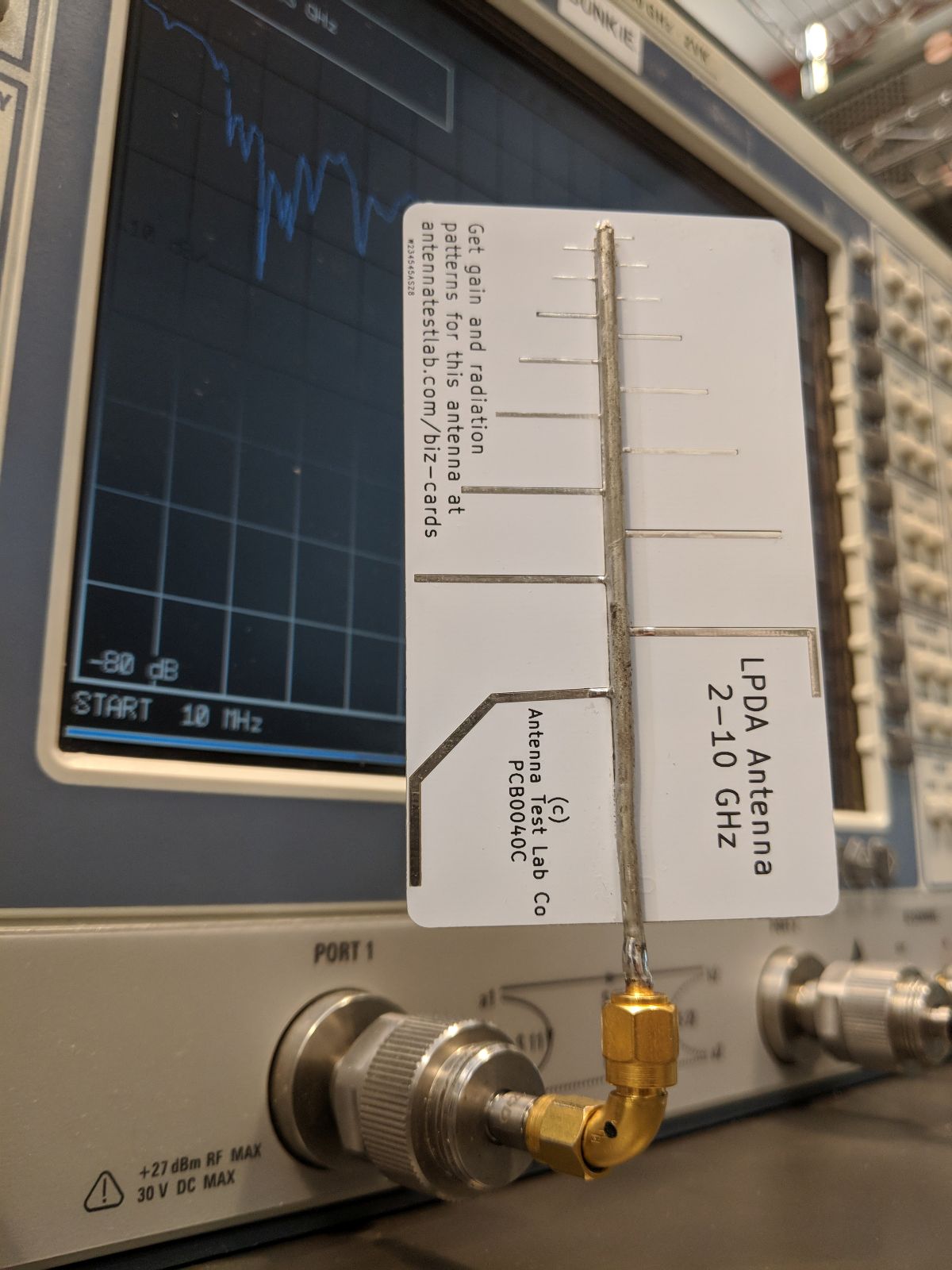
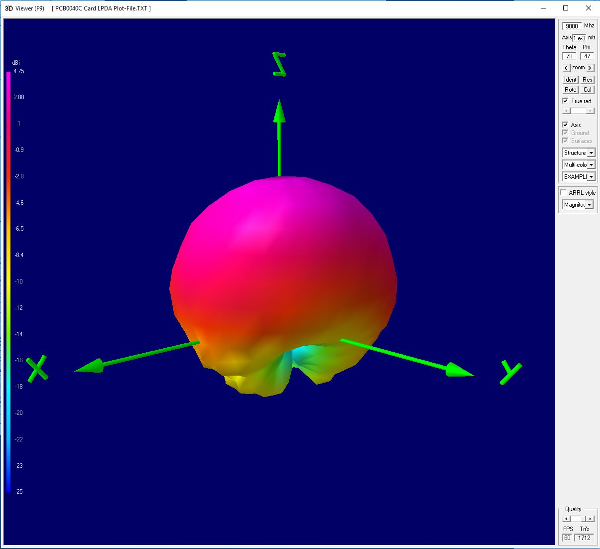
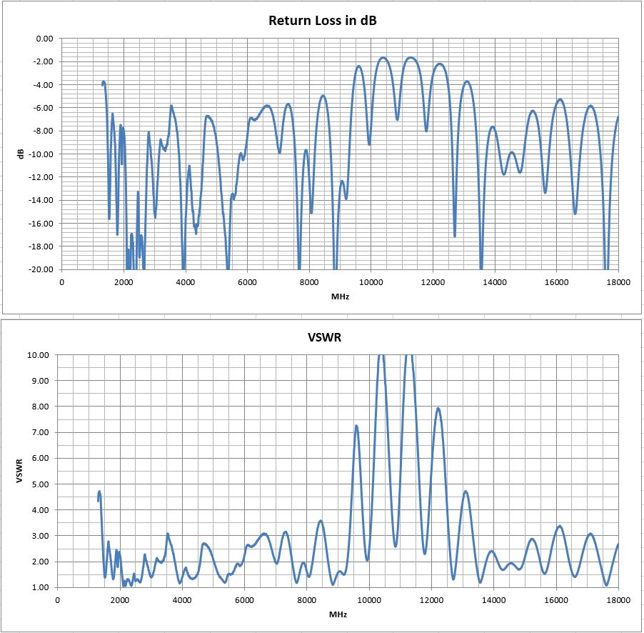
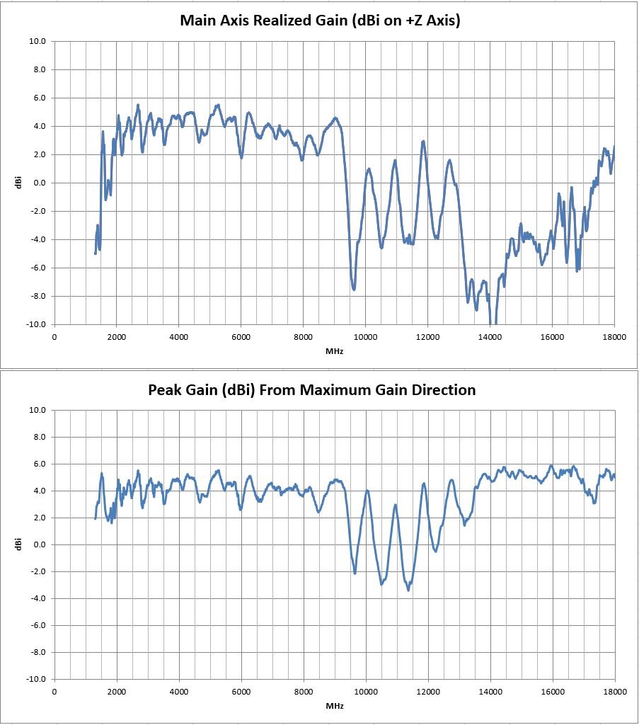
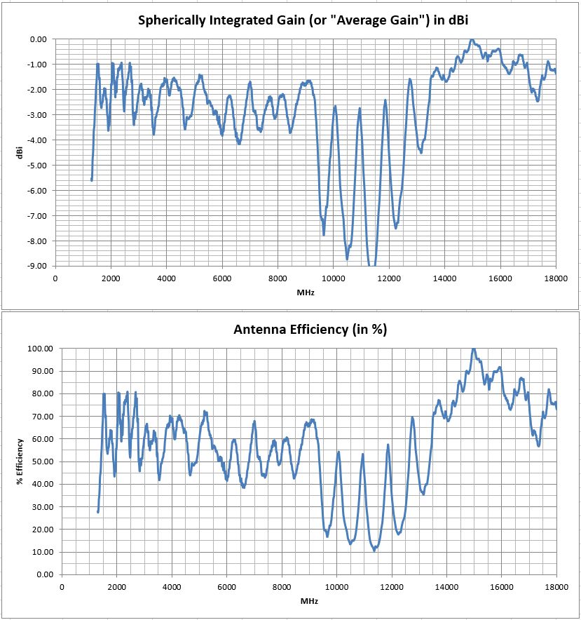
This functional business-card sized antenna works well from about 2 to 10 GHz, and is useful from 1500 MHz up through 18 GHz.
It is fed by a soldered down section of semi-rigid coax as shown in the photographs below. For convenience, just use a scrap of coax that is already terminated with an SMA connector. Log Periodic Dipole Array antennas have a range of resonant elements that work over a broad frequency range. LPDAs are fed from the “front” of the antenna, and its directivity is towards the “small elements end” of the card. The feed-line exits from the rear of the antenna as shown.
A full Excel spreadsheet 3D gain results report can be downloaded HERE. This extensive test program covers full 3D spherical gain patterns at 1671 stepped frequencies from 1300 MHz to 18 GHz in 10 MHz steps. The test report details higher level performance data, such as: Forward Gain, Peak Gain, Radiation Efficiency, and VSWR/Return-Loss vs Frequency.
The full set of 1671 spherical plot-files can be downloaded HERE in “zipped” format. Unzip and use this plot-file along with our downloadable 3D plotting software HERE. Then create rotate-able/scale-able 3D plots on your own desktop at any test frequency.
Please remember – We can test your antenna project too! We have a full range of services listed HERE
We hope you enjoy your sample antenna. We do not offer antenna design services here so that we may focus customer design confidentiality. These “biz card” antennas are just for fun, and they are not for sale. Inspiration for this PCB design came from Kent Britain WA5VJB, who does sell PCB antennas. His website is HERE.
Biz Cards
We have been using PCBs as business cards for years and our customers love them! Why not make an antenna AND a biz-card! It’s been so much fun that we have even done some 100mm x 100mm PCB antenna tiles as giveaways.
If you’ve come here, you’re probably curious about your antenna card. In addition to creating all of these fun designs, we thoroughly evaluated all of the in the anechoic chamber. The card you have is a functional antenna, and only requires a connector or a feed line. All you have to do is read the PCB number on the artwork and select the model from our list below. There you will find instructions on how to feed the antenna and what topology it uses. And what you really need to see, are the sample 2D Polar or full 3D evaluations. This is the same testing that we can do for your antenna project!


What is an Anechoic Chamber?
The Basics
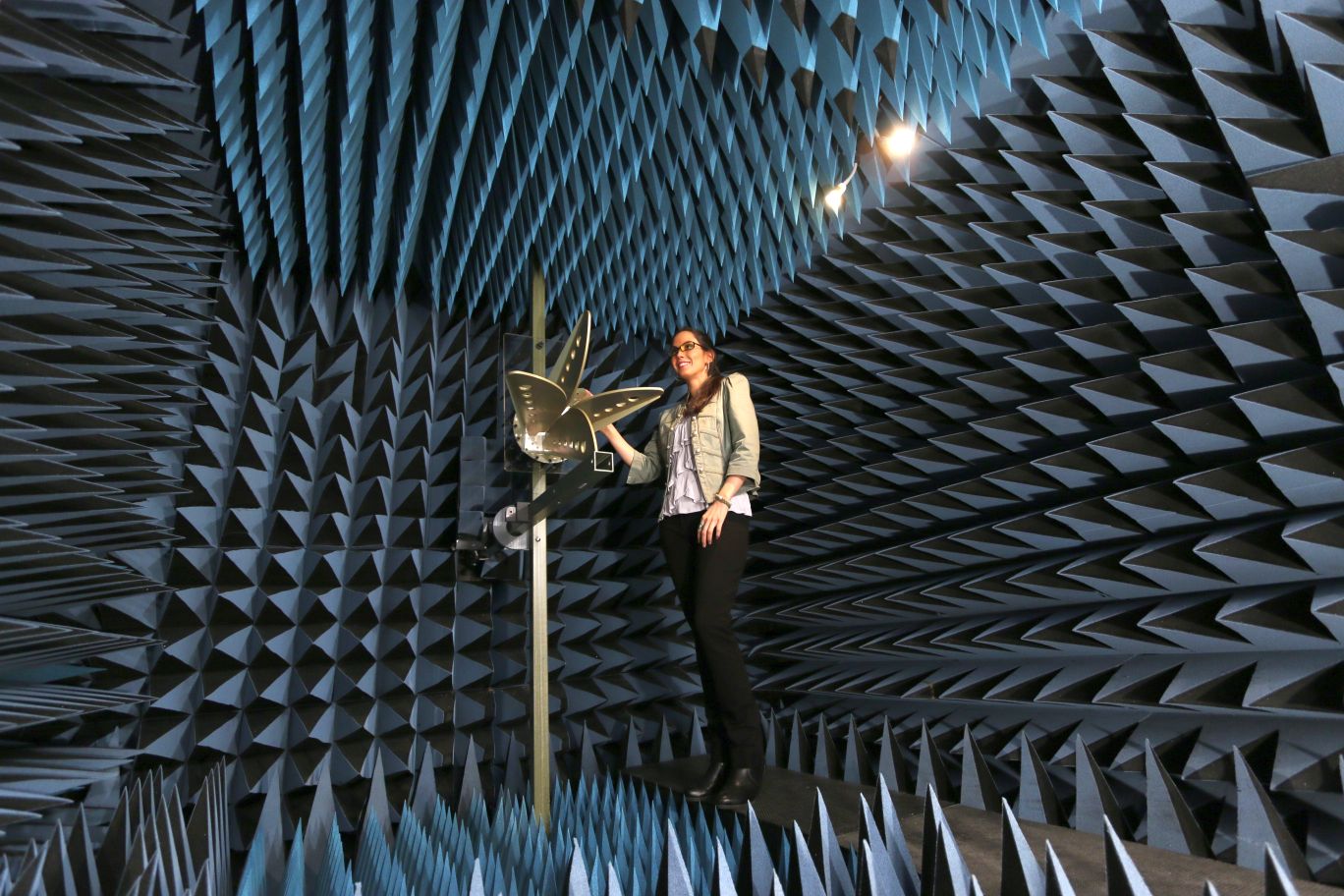
An anechoic chamber is a shielded room that has radio-wave absorbing material applied to the walls, ceiling, and floor. Chambers may be table top sized enclosures, but are normally room sized enclosures where engineers can walk in and work. The absorbers on the inside surfaces are often pyramidal shape, and give the room an unique “science fiction” look. You may have also heard that they are very expensive. So why would anyone go to all of this trouble? Because there are many benefits to antenna testing!
The Flashlight Comparison
At Antenna Test Lab Co, we often find that comparing antennas and radio waves to light is helpful in our customer’s understanding of basic concepts. We often illustrate the anechoic chamber’s functionality with the following flashlight comparison.
Imagine your task was to “pattern” a flashlight. In other words, your job is to measure and create a diagram of where the device shines light, where it does not, and how much light goes where. It may seem intuitive, because you have eyes and you can intuitively look at your flashlight. We are used to simply “seeing” light and it’s patterns, so it is easy to visualize a flashlight’s pattern.
However, we cannot see radio wave energy directly, so we have to measure it with radio receivers and antennas. Luckily, the propagation is very similar, so just continue to visualize light from the flashlight. Now back to your task … patterning the flashlight. Imagine that you are blind, but you have a light-meter. You can use it to measure the flashlight’s output in various directions to create the pattern of the flashlight beam. We would be using an antenna and a receiver to do the same for patterning an antenna.
You start the job and quickly discover that your light meter readings are being interfered with by the sun. Outdoors on a sunny day, your light meter is picking up lots of sunlight, and confusing that with the flashlight’s light. You need “shielding”.
Shielding
So you go indoors, to a windowless room, with the lights turned off. In this “dark room”, all of the observed light is from your flashlight under test. The room is shielded against outside light, just like the metal walls of an anechoic chamber shield our equipment from the outside radio signals. This would be the perfect solution, if it were not for one problem… reflections !
Reflections
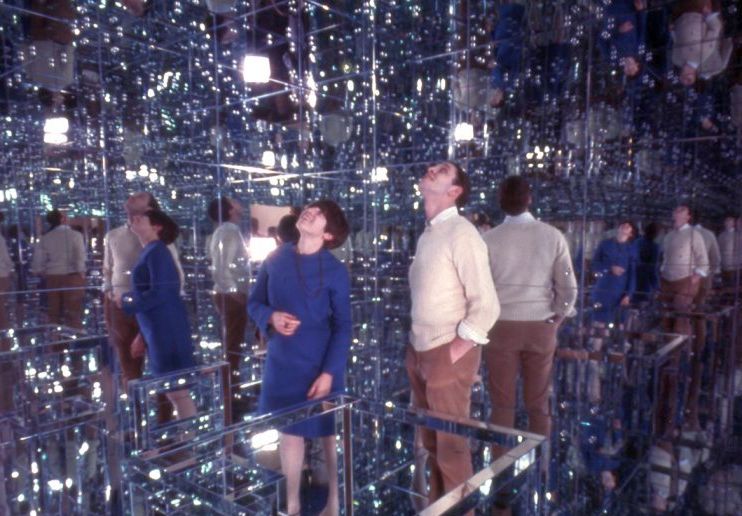
Imagine the dark room you just chose was lined with mirrors. It is still a “dark room” and it is still fully shielded from outside light. However, the mirrored wall/ceiling/floor reflections will cause chaos with your flashlight measurements. What can be done?
You decide to paint over the mirrors with a flat black paint, one that absorbs lots of light. Now you have an optical anechoic chamber. No more reflections, or echoes. The word anechoic means without echoes. Now your test flashlight appears to be in free-space. There is no ambient light, and the walls are not visible.
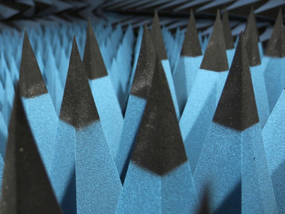
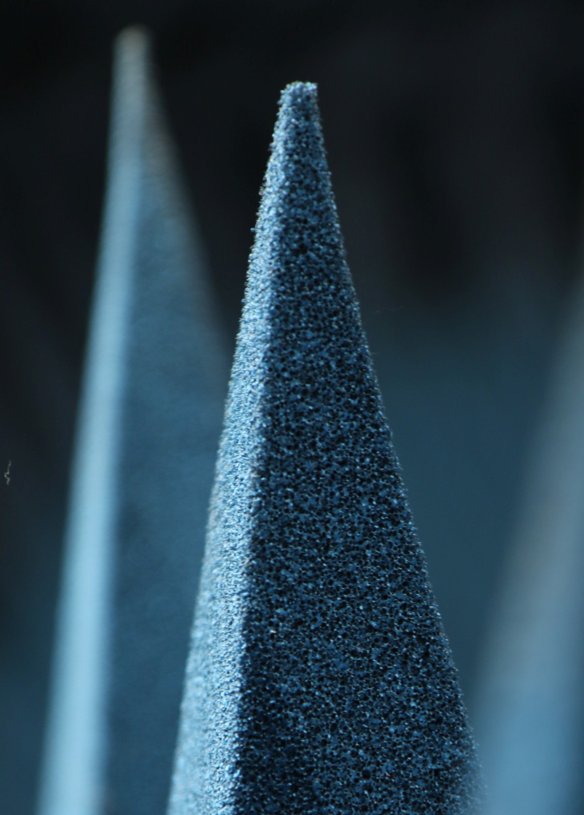
In the RF world, the reflective walls of the metallic shielded room are rendered “invisible” or “anechoic” by covering them with special RF absorbing materials. The most common absorber is the carbon loaded foam pyramid. Sharp tips on the absorbers keep RF waves from bouncing off, allowing the radio waves to slowly transition from air to the lossy carbon inside of the foam. This gradual taper from tip to core is the secret to RF absorbers. The amount of RF that bounces off of anechoic chamber walls is often 0.1% to 1% (-30 to -20 dB) of the original wave. The low level of reflections in our chamber allow us to accurately measure your antenna’s gain, efficiency, and radiation patterns. Find out more about how we do it in this educational article.
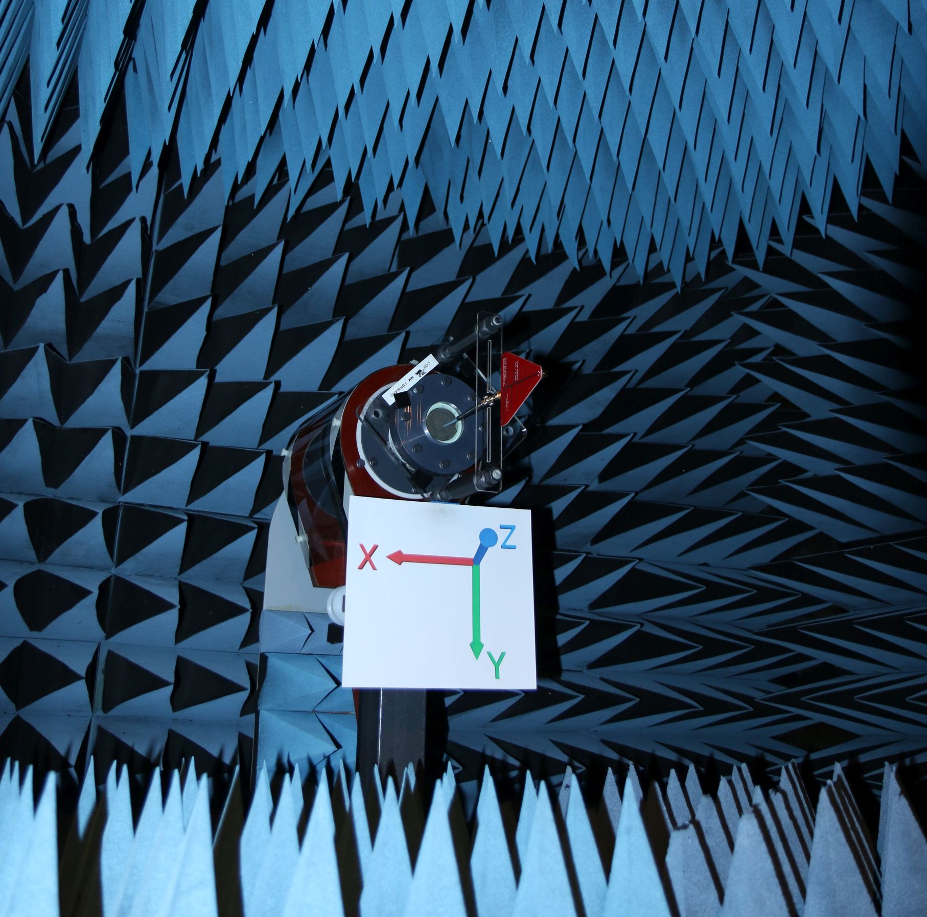
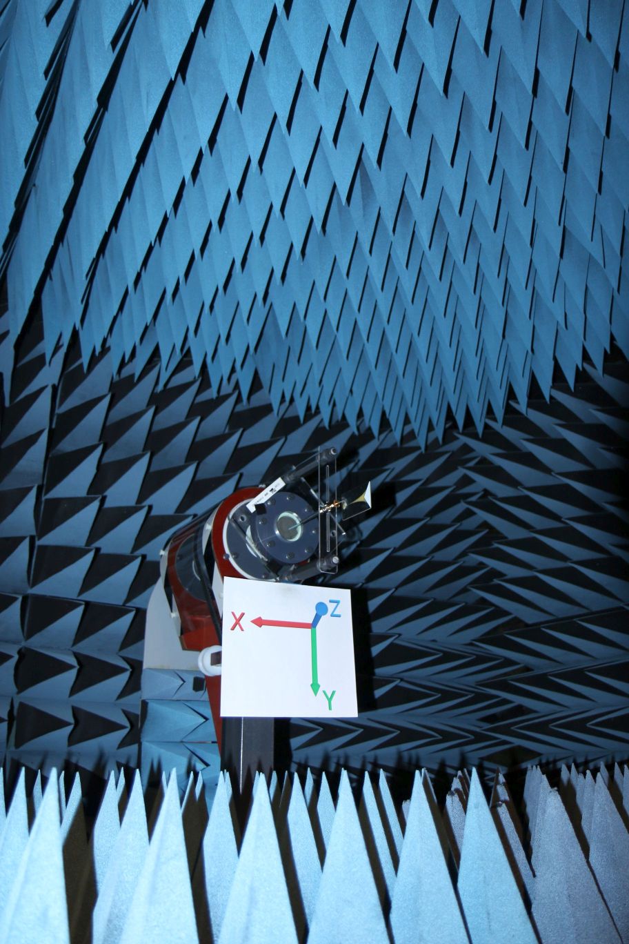
Our Anechoic Chamber
The walls, ceiling, and floor of our chamber are treated with over 2000 absorbing pyramids! The absorbers are between 12″ and 18″ long. We have an additional absorber in our chamber, 12,000 pounds of ferrite tile. The ferrite tiles absorb RF at frequencies too low for the foam pyramids, and extend the anechoic ability of our chamber down to frequencies far below many antenna testing chambers. We routinely test antennas down to 300 MHz, and product emissions down to 30 MHz.
See It For Yourself
Drop us a note, and see how we can help get your antenna project and costs on track ! Many successful companies partner with an antenna testing service, and reap the benefits.
The Benefits of Testing Your Antenna
Success
Your customers will rely on your antennas to perform well in their system, and your product’s success relies on this too. Most hardware and software is thoughtfully tested before sale or deployment, but why are many antennas ignored? The risks to system functionality and your customer’s trust hangs in the balance if you skip your antenna verification. However, there is no reason to defer your antenna evaluation, help is available. We offer full antenna testing services and free educational articles.
The results of an anechoic chamber antenna evaluation can provide insight and confidence throughout your company: from design engineering; parts procurement; right through to field support and customer success.
PCB Layout
If you layout your own trace copper antennas or PCB mount component antennas, then board-level antenna testing will allow you to understand the immediate environmental effects of parts placement, enclosures, ground-planes, batteries, PCBs, or cables. If you buy your antenna, beware … component antennas are often overly optimistically specified by their manufacturers to compete with each other on gain numbers. They ignore the real world compromises designers must make during implementation and layout. Whether you create/duplicate your own PCB antenna or buy a part, the same risks of non-testing apply – and often lead to impaired wireless system performance and poor product reputations.
PCB layout “realities” such as crowding and proximity to objects like cables, batteries, or enclosures can have a dramatic impact on RF performance. Definitely follow the antenna manufacturer’s guidelines, but take note of your design constraints on these best practices. Don’t be tempted to believe that your antenna implementation will perform like the antenna’s data sheet or “demo board”. And please remember, more gain is not always better.
Matching
The feeding and matching of small embedded antennas can be tricky to optimize, more so if you keep yourself “in the dark”. Wishful thinking is not a good system test practice, so why not verify your antenna implementation? It is all too common that poor antenna implementation goes ignored and untested. However, your customers will always notice poor performance! Master and optimize your design early in its product cycle with a simple antenna evaluation. An iteration or two of anechoic chamber testing can verify your antenna and your RF link, the same way you verify your other design elements. “Bench checks” conveniently generate false confidence, while test laboratory far-field testing ensures success. Tuning or matching networks may appear to offer great broadband return loss to your VNA, while often yielding poor radiation efficiency (under 10%). Get the facts !

Services
A 3D far-field antenna evaluation will reveal your product’s complete antenna pattern, gains, radiation efficiency, circularity, axial ratio, and many other quantified performance parameters swept over frequency. You can go well beyond that “sales pitch” gain number from an antenna part’s spec sheet (or design formulas), and realize operational insight. Only then, can you have confidence in your wireless link.
If you import finished antennas, chamber testing allows you to verify their quality and specification compliance, especially on those large buys from low cost offshore sources. If you design antennas, then realize their final verification through chamber testing. Go beyond those simulations and bench checks on all new antennas or out-sourced designs. Your customers trust test results, not simulations and promises.
Evaluations
Your antenna will ultimately cripple or enhance your wireless product’s success, so why leave it all to chance? Expert antenna testing services are easily available, cost effective, and timely. Antenna Test Lab Co will work hard to give you the insight you need for a successful wireless product.
Practical antenna testing can be complex, and definitely requires elaborate equipment, facilities, and specialized knowledge. However, the task is easily handed off to our specialized laboratory, and our engineers evaluate a wide variety of antennas daily. Antenna Test Laboratory Co can evaluate your antenna within days and provide full performance data, as well as boost your understanding and confidence. Full evaluations are available from only $525.
The 3D Spherical Coordinate System
Understanding Spherical Coordinates
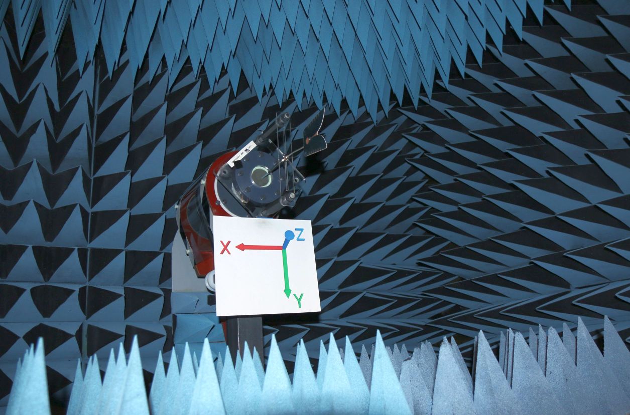
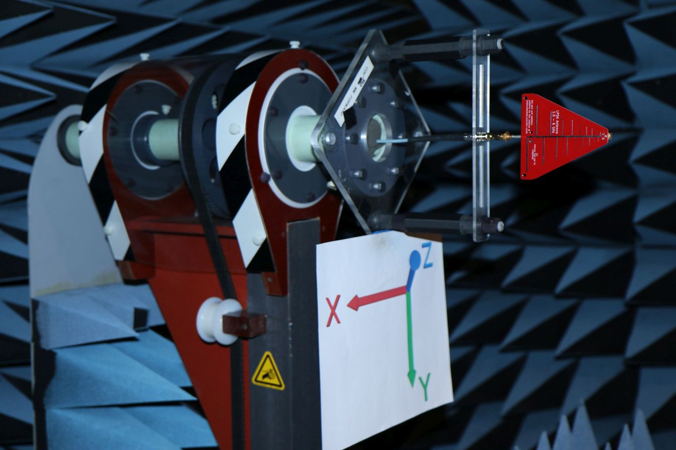
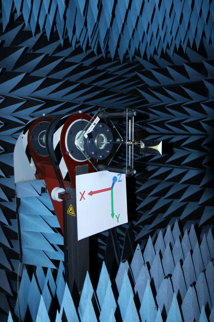
Antenna Test Lab Co performs 3D spherical evaluations using Phi axis (roll) and Theta (turntable) stepping per the “Great Circle Cut System”. This way, native results are available directly in the standard preferred spherical coordinate system.
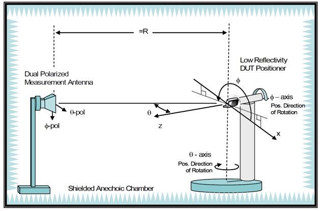
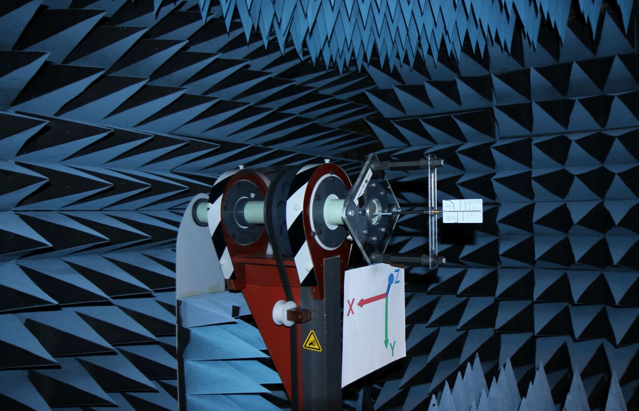
This enlargeable figure shows the Theta axis (turntable or azimuth control) with the Phi axis “roll positioner” (or elevation control) on top of it. Our positioners are fiber-optically controlled, and made of all plastic materials so as not to absorb RF energy. The rate of turn is 3 RPM (20 seconds) with a positioning accuracy of better than 0.1 degree. Our Photos of the laboratory show sample mounting arrangements for various items. Our chamber antennas can cover 300 MHz to 40 GHz. For increased throughput speed, our lab uses three-port VNA measurements and quad ridge horns to simultaneously take vertical and horizontal polarized antenna gain measurements.
It may sound complicated, but it is not. You can download our 3D plotting software here. Then download one of the 3D tested example antennas and make your own desktop plots. You could start with Example #1. You can even brush up on antenna testing methods and terminology here.
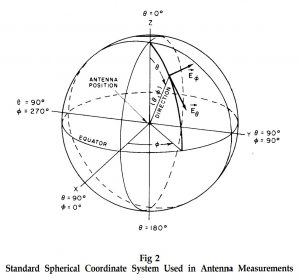
Measurements are logged in tables of Theta and Phi spherical coordinates, per IEEE Std 149-1979, “Test Procedures for Antennas”. The standard IEEE antenna coordinate system is illustrated below. The spherical coordinates relate to the Cartesian axes as shown in the click-to-enlarge diagram to the left.
Evaluate Your Antenna
Ready to find out more about your antenna … partner with an antenna evaluation company and never be “in the dark” again! Contact us here.