- +1 919 200-0292
- info@antennatestlab.com

Pattern Angular Resolution
Search results for:
Pattern Angular Resolution
Detail Levels And Pattern Sizes
If you are used to looking at electromagnetic simulator outputs, then a 1 or 2 degree resolution may seem normal. In reality, this could translate into 50,000 physical test directions… way too expensive and time consuming for real antenna test programs. The graphic examples below illustrate increasing test resolution of a real horn antenna’s gain pattern, and conclude with two realistic test resolutions (10 and 5 degrees). We offer 10 degree resolution patterns as a standard for 3D plotting, and we commonly do 5 degree patterns too. Please Contact Us with your requirements or questions. Find out the benefits of measuring your antenna here!
 |
30 Degree Resolution (91 point spherical grid), crude 3D visualization |
 |
20 Degree Resolution (190 point spherical grid), coarse grid size for 3D visualization |
 |
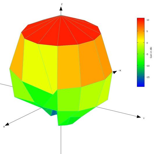
10 Degree Resolution (703 point spherical grid), still practical test times while very good for 3D visualization |
 |
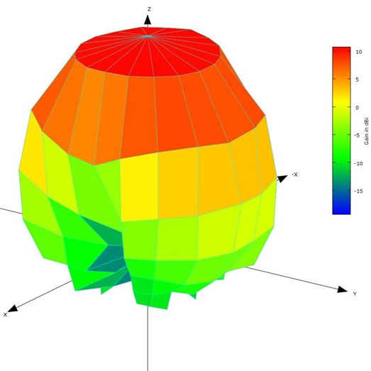
5 Degree Resolution (2701 point spherical grid), longer test time, for very detailed plots; Great for complex or high-directivity patterns; These plots are also preferred for publication or antenna marketing; At frequencies above 10 GHz, directional antennas (especially horns with gain >15 dBi) should be tested with 5 degrees of angular resolution |
(The 3D plots above are all click to enlarge.)
Your Antenna
Want to find out what your antenna pattern looks like? Partner with an antenna testing company and get results! Contact us here.
Far Field Testing
Two Antenna Testing Methods
Our test lab measures all customer antennas by exciting them with our swept VNA sources and observing their response with a quad-ridge antenna at the other end of our anechoic chamber, usually 12 feet away. This is called far field testing, because we observe your antenna’s actual performance from a significant distance.
Far Field Testing
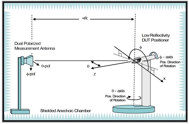
Far field testing is an accurate and natural way to evaluate antennas. It makes makes no assumptions about their operation and involves no simulations or predictions. It also quantifies feed-line radiation and other unexpected distortions which happen near the antenna.
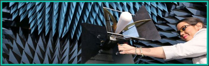
Near Field Testing
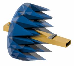
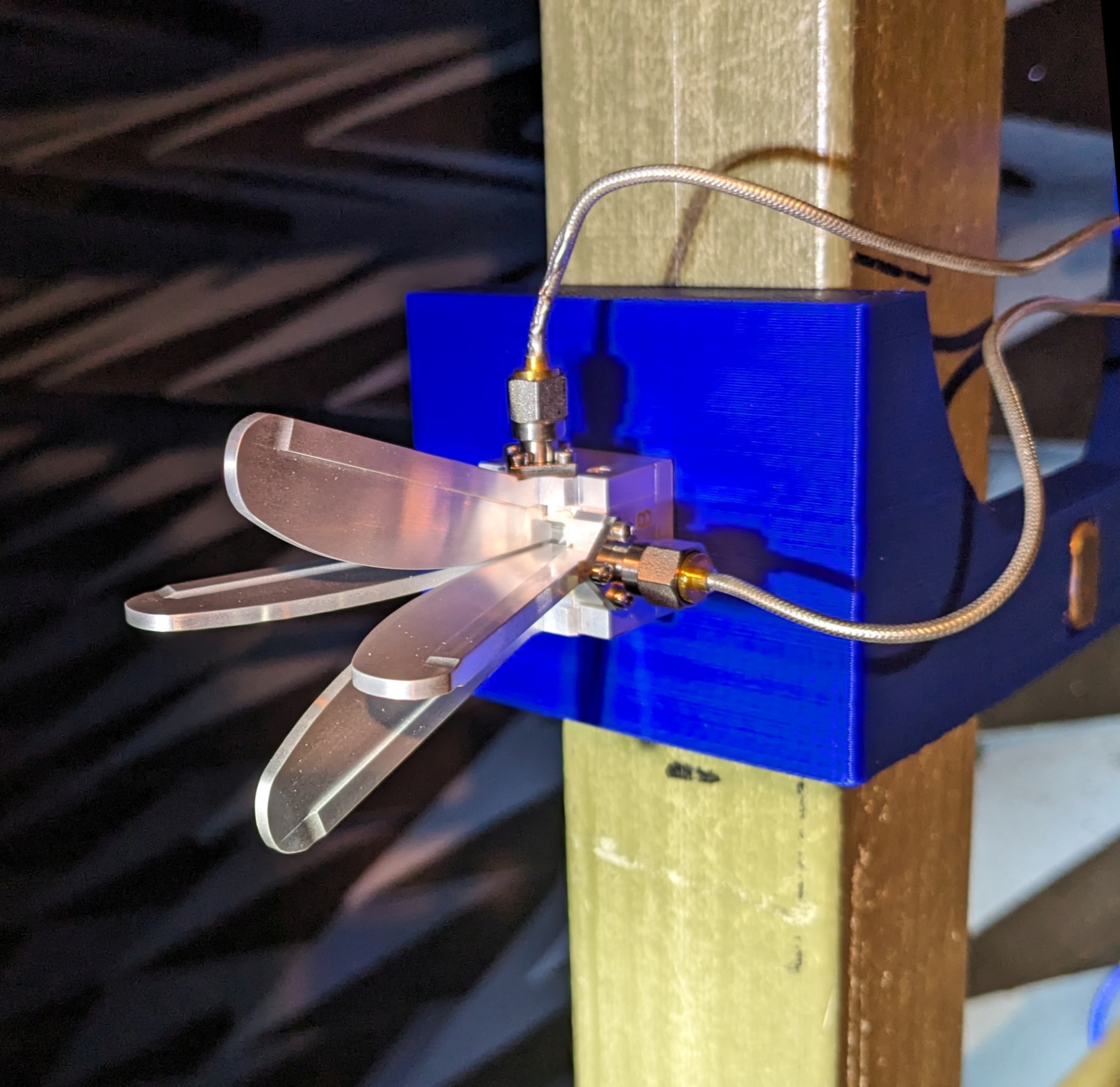
Smaller chambers sometimes use “near field scanning”. In this method, a probe (like this one shown) is scanned near and around the antenna under test. The probe results are run through a mathematical algorithm to predict the far field pattern of the antenna. This method may miss many real world antenna effects such as feed-line distortions. It can be less expensive, and does not require a large anechoic chamber. It is well suited to large aperture antennas that have challenging far field requirements.
Let’s Get Started !
Ready to get your antenna project underway … then contact us and let us help. A qualified antenna testing company will get your project on track.
Example Test Reports Overview
Free Samples Of Our Work
Our antenna testing service has evaluated countless interesting customer antenna projects. However, we always hold that data completely confidential. We even refrain from antenna offering design services, to guarantee confidentiality of your intellectual property.
Our antenna testing company has evaluated lots of interesting public domain antennas purchased on the open market. These examples can help you decide on which pattern type and resolution are best for your product. Learn more about 2D vs 3D antenna testing here, and discover the many benefits of testing your antenna here.
You can download our 3D plotting software here. Then download one of the 3D tested example antennas and make your own desktop plots. You could start with Example #1. Here is the link to our gallery of Example Reports for easy browsing of our sample projects.
Let’s Get Started !
Want to get started? Simply contact us and tell us about your project.
Download 3D Plotting Software
Desktop 3D Antenna Pattern Plotting
Free space testing of antennas (or live transmitters with embedded antennas) can create vast data-sets with hundreds of thousands of gain measurements. Our customers enjoy 3D plots on their own desktop computers, allowing 2D/3D pattern rotation, scaling, and access to the entire frequency range of their test program. Antenna Test Lab presents the following software for viewing your measured 3D antenna patterns.
We have partnered with Arie Voors, the author of the very popular antenna simulator called “4NEC2”. Our customers may utilize this software for antenna simulation, but most importantly, it has been updated to allow plotting of our 3D measured spherical test data. Following these steps will help you install this free 4NEC2 software on your PC.
Step By Step
(1) Download the latest 4NEC2 version from HERE, under Downloads => “Latest 4nec2 version” (do not choose the “no install version”).
(2) Install it (move the folder) on your PC to any desired location, and note this location.
(3) The full User Manual is “4Nec2.rtf”, and is located in the same installed folder; We have PDFs here
(4) The first time you run 4Nec2, you will be asked to load a model, and you can find them in the /models folder (you may load any of its included examples, and you won’t actually use the model).
(5) Download and unzip this zipped file to try out one of our 3D plot-files (use 850 MHz), unless you already have test results from us.
(6) To import 3D data into the 4NEC2 viewer, just select Main>File>Import Far-field data>Full/3D data (*.txt) from the main menu… then navigate to your TXT plot-files.
(7) If your imported data set contains more than one frequency, you will be asked to type in one frequency (in MHz). You can always use “Notepad” or any other text editor to examine your *.txt file and see which frequencies it contains.
(8) You will see a 2D polar graph by default, then select Main (F2) : Window>3D viewer (F9) to open the 3D viewer window. The spherical pattern is hidden by default, and can be enabled by changing the pull down menu from “Hide pattern” to “Multi color”.
(9) Going Further: Explore antenna testing techniques and terminology in our Educational Section.
Active Antennas and EIRP/TRP (in dBm)
Transmitter Patterns, EIRP, and TRP
The preferred test method for evaluating a “live antenna” or active transmitter performance, is far field power (EIRP) measurements. We use our calibrated chamber paths and positioners to map out your device’s EIRP in dBm. With this method, your pattern shows EIRP (apparent power) in hundreds of test directions. This type of pattern is a typical final test of a transmitter or transceiver with an integrated or attached antenna. Any issues with antenna performance or the matching network will be discovered. We will also calculate the Total Radiated Power (TRP) of your transmitter, based on the spherically integrated EIRPs in any 3D pattern.
TRP Example
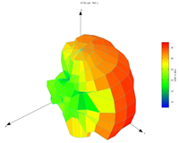
The shape to the left is the EIRP pattern of a 2 Watt (+33 dBm) GSM cellular modem. The device is supposed to be omnidirectional, but the pattern shows otherwise. Also, this device has an FCC mandated maximum peak EIRP of 4 Watts (+36 dBm), which can be seen to be exceeded in the “-X axis” direction of the 3D plot. We also calculate Total Radiated Power (TRP) by integrating over the surface of the spherical pattern. Knowing your TRP along with your conducted launched power, allows antenna radiation efficiency to be calculated. Many modern “wireless” products seek ultra small antennas, and antenna+matching efficiencies can sometimes be very poor (10 to 20%).
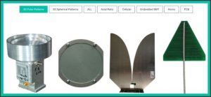
1D vs. 2D vs. 3D vs. 4 Dimensional Patterns
How To Choose Your Antenna Pattern Type
Once you have decided to get your antenna “patterned”, you are well on your way to new insights into its performance and suitability for your application. But should you get traditional 2-Dimensional polar plots or 3-Dimensional Spherical plots? The answer usually lies in your antenna type, and it’s expected performance.
Well behaved, directional, or highly symmetrical antennas can be tested with 2D polar plots. Omni-directional, unknown, or newly designed antennas should be evaluated with 3D spherical patterns. A spherical pattern does not miss flaws or unexpected disturbances in patterns that can come from feed line, enclosure, or PCB edge interaction. We always recommend 3D patterns, unless your antenna is already understood. Below is a comparative summary of 2D vs 3D patterning.
We can also do 1D testing: One dimensional testing is simply measuring an antenna’s gain over swept frequency in one direction. And if you want 4 “dimensions” we can do that too. Using custom MATLAB scripts we create animated 3D plots, where time is used in the animation to display your frequency sweep. In a 4D pattern, your 3D pattern evolves as frequency is incremented and displayed. We have awesome examples HERE.
2D Polar Plots |
3D Spherical Plots |
|---|---|
|
|
|
Higher angular resolution (detail), but only in the chosen “cuts” (usually Elevation/Azimuth or E&H Plane) |
Lower resolution, but spread over the entire radiation sphere |
Reveals sharp peaks and nulls in highly directional or microwave antennas, missing details outside of the prime measurement planes |
Reveals distortions and unexpected pattern effects, nothing is missed by exploring the entire sphere |
Cannot calculate radiation efficiency, since the entire sphere is not explored |
Customers receive a spherical integration of their 3D patterns, which we present as a radiation efficiency vs. frequency graph |
2D Is Best Suited For These Types Of Antennas: |
3D Is Best Suited For These Types Of Antennas: |
Horns, Yagi’s, Log Periodics, Monopoles, Patches |
Any PCB mounted/soldered device, PIFA, Loops, Zig-Zags, Coils, “Chip Antennas”, SMT/SMD |
High gain (directional), Microwave |
Virtually all embedded antennas, omni-directional antennas, any antenna with suspected or unknown feedline interaction (i.e. no balun) |
Ultimately, the best way to decide which pattern type is best for you is to Contact Us with your antenna test goals. We will help you decide which additional measurements are crucial for your application, like efficiency, front-to-back ratio, front-to-rear ratio, peak gain, or circularly polarized parameters like LHCP/RHCP gain or axial ratio.
Articles, Education, And Tutorials
The following tutorial pages have been created to help our antenna testing service’s customers understand far field antenna evaluations at our facility. Please contact us with your test requirements or any other project questions.
Our Educational Articles:
- The Many Benefits of Testing Your Antenna
- Should I Choose a 2D or 3D Antenna Pattern ?
- About Circularly Polarized Antenna Testing
- What is Antenna Gain and dBi ?
- How is Antenna Gain Measured ?
- Is More Gain Better ?
- What is an Anechoic Chamber?
- Live Antenna or Transmitter Pattern Testing
- What Are Far Field testing and Near Field Tests
- The Basics of Return Loss and VSWR
- Pattern Resolution Examples
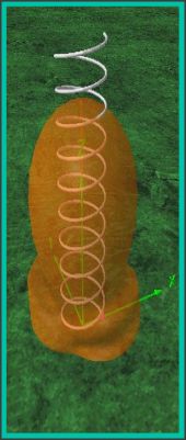
- The Spherical 3D Coordinate System
- 3D Plotting Software Downloads (this is also a great free wire-antenna simulator)
- Example Reports and Antenna Tests Results
We have lots of example RF antenna test results available on our examples page. To find out how we can help, just ask !
Our Published Articles
Providing antenna insights is our passion! Here is a collection of some of our published articles.
There lots of sample antenna test reports and patterns available.
To find out how we can help, just ask !
Our Test Frequency Capabilities
Continuous Sweeps For Your Antenna Testing Projects
Broadband Open Boundary Dual Ridge Dielectric Lens Reference Horn With Mirror
Customer interest in testing single frequency antennas is now rare. All test projects benefit from swept tests that cover the intended operating band(s) and beyond. Testing outside of the operating band(s) can sometimes reveal tuning issues with antennas, as well as future-proof your data when operating specifications expand.
When testing via the gain substitution method, the maximum possible sweep ranges are dictated by the overlapping ranges of the calibrated reference antenna chosen, and the quad-ridge chamber antenna available. Our antenna testing service features the widest broad band antennas available.
Our Three Ultra-Wide Maximum Sweep Ranges:
-
300 – 6000 MHz
-
1.5 – 18 GHz
-
4 – 40 GHz (up to 43.5 GHz over-range)
Of course, any subset of these ranges is often more useful. For example, a test program for many cellular antennas is 600 to 2700 MHz every 10 MHz (211 steps). This means there are 211 “patterns” available for plotting or viewing on your desktop. If this were a 3D spherical test program, customers would also receive a graph of radiation efficiency vs frequency from 600 to 2700 MHz. Want to know more, please explore our Educational Section. We would love to talk, just contact us and tell us about your project. Our antenna testing company has been built on helping customers !
Our Partners
Our Promise Of Confidentiality
We do not offer antenna design services. After having signed countless NDAs with trusted customers, it would be improper for us to offer design services, while simultaneously evaluating similar designs from your competitors. Our commitment to our customer’s intellectual privacy is paramount.
However, there are a few top-notch RF consulting companies who frequently utilize our laboratory, and they are well suited to the task of product design consulting and test program management. The first three are highly recommended to customers seeking comprehensive design services for RF, “Wireless”, M2M products and antenna design.

Additional Resources For RF Engineers
There are many resources on the web for RF and antenna engineers. Please start with our educational articles, this is the same advice that we give customers here in the lab, and they will get you up to speed.